Method for manufacturing a continuous-length switch

a technology of continuous length and switch, which is applied in the direction of insulated conductors, cables, instruments, etc., can solve the problems of difficult to cause buckling and the like of switches, and achieve the effects of improving operational efficiency, minimizing power requirements, and excellent safety and reliability

Inactive Publication Date: 2005-05-31
IDEC CORPORATION
View PDF13 Cites 10 Cited by
  • Summary
  • Abstract
  • Description
  • Claims
  • Application Information

AI Technical Summary

Benefits of technology

[0054]The present invention can offer a continuous-length switch which is excellent in safety and reliability, eliminates the need for a cumbersome secondary working, allows improvement of the operational efficiency during manufacturing, and can minimize a power requirement.
[0055]The present invention can offer a continuous-length switch which is difficult to be short-circuited and is excellent in safety and reliability. Also, if winding up or the like of the switch is carried out, buckling and the like of the switch are difficult to be caused. Therefore, the restriction in handling of the switch can be loosened, and winding the switch around a drum for transportation and storage is allowed, thereby resulting in the operability of the switch being improved and a space requirement being reduced.
[0056]The present invention can offer a continuous-length switch which is excellent in durability, and will not fail after a long period of use.

Problems solved by technology

Also, if winding up or the like of the switch is carried out, buckling and the like of the switch are difficult to be caused.

Method used


Image

  • Method for manufacturing a continuous-length switch
  • Method for manufacturing a continuous-length switch
  • Method for manufacturing a continuous-length switch

Examples


embodiment 1

[0102

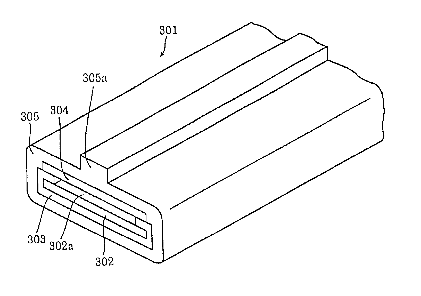
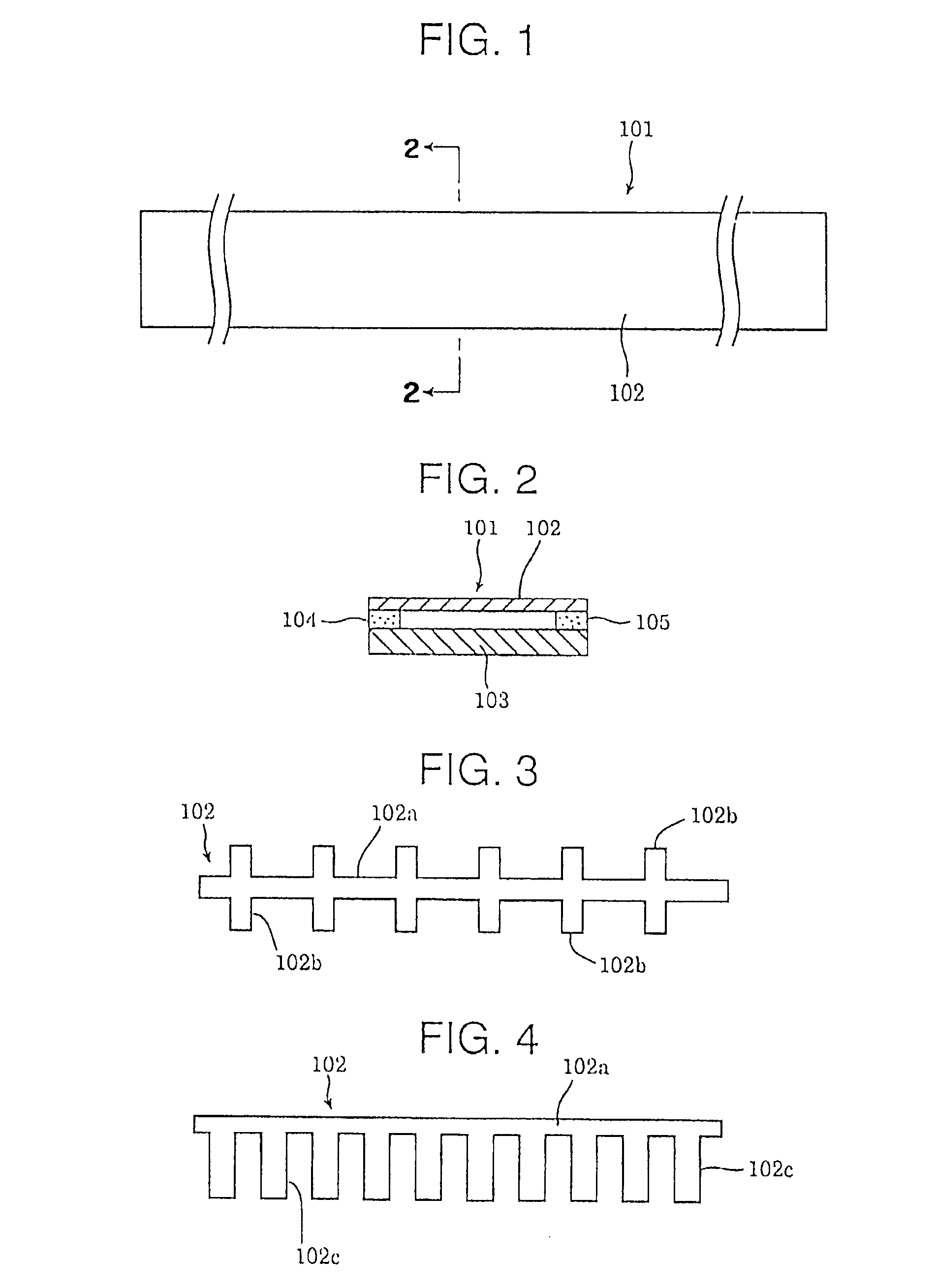
[0103]FIG. 1 and FIG. 2 show a continuous-length switch 101 according to a first embodiment of the present invention, in which a continuous-length and elastic upper electrode plate 102 and lower electrode plate 103 are disposed. The plates 102 and 103 oppose each other and sandwich a pair of continuous-length insulators 104 and 105 that extend along a longitudinal direction of the plates. A switching function is provided when the action of an external force F applied by an operator, a subject, or the like causes the upper electrode plate 102 to be deflected and contacted with the lower electrode plate 103.

[0104]Next, with reference to FIG. 3 to FIG. 13, various examples of the geometry of the upper electrode plate 102 will be described.

[0105]With the geometry of the upper electrode plate 102 as shown in FIG. 3, a number of protrusions 102b are formed at fixed intervals, which extend from a linear conductive portion 102a, that continues in the longitudinal direction, toward the ...

embodiment 2

[0114

[0115]Next, with reference to FIG. 5 to FIG. 13, the continuous-length switch according to a second embodiment of the present invention will be described.

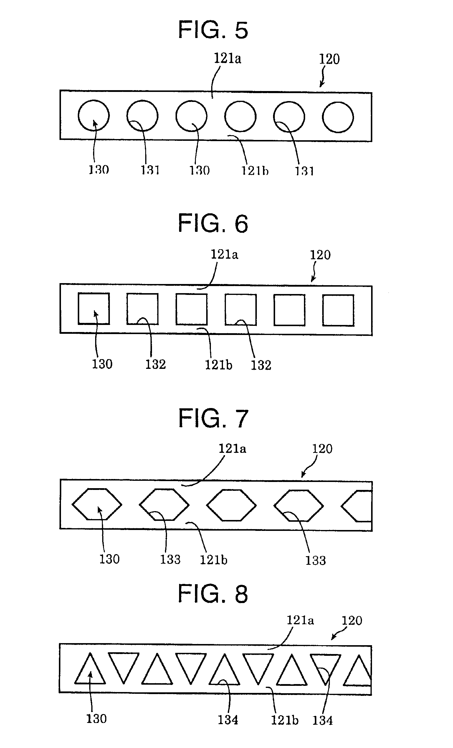
[0116]The basic configuration of the continuous-length switch according to the second embodiment is the same as that of the continuous-length switch according to the first embodiment, except that, as shown in FIG. 5 to FIG. 13, an upper electrode plate 120 in the continuous-length switch has a linear conductive portion 121a, 121b at both side areas along the longitudinal direction of the electrode plate, and between the linear conductive portions 121a and 121b, non-conductive portions 130 having any one of the various geometries as stated below are formed.

[0117]FIG. 5 shows an example in which the upper electrode plate 120 is provided with a number of circular holes 131 as the non-conductive portions 130; FIG. 6 shows an example in which the upper electrode plate 120 is provided with a number of square holes 132 as the non-con...

embodiment 3

[0124

[0125]FIG. 16 and FIG. 17 show a continuous-length switch 201 according to a third embodiment of the present invention, in which a continuous-length and elastic upper electrode plate 202 and lower electrode plate 203 are disposed. The plates 202 and 203 oppose each other and sandwich a pair of continuous-length insulators 204 and 205 that extend along a longitudinal direction of the plates. A switching function is provided when the action of an external force F applied by an operator, a subject, or the like causes the upper electrode plate 202 to be deflected and contacted with the lower electrode plate 203.

[0126]FIG. 16 is a plan view illustrating one example of a geometry of the upper electrode plate 202. The upper electrode plate 202 is provided with a number of, for example, hexagonal holes 207a at fixed intervals as non-conductive portions, and at both upper and lower sides of each hexagonal hole 207a in FIG. 16, a linear conductive portion along the longitudinal direction...


PUM

PropertyMeasurementUnit
heightaaaaaaaaaa
thicknessaaaaaaaaaa
conductiveaaaaaaaaaa

Abstract

Disclosed is a method for manufacturing a continuous-length switch that comprises first and second electrodes. The method comprises covering at least a first surface of a first electrode with an insulating material. Then, a portion of the insulating material from the first surface of the first electrode is removed so as to provide an exposed portion of the first electrode. And then, a second electrode is placed on the insulating material and over the exposed portion of the first electrode.

Description

[0001]This application is a divisional of U.S. application Ser. No. 09 / 572,696, filed May 16, 2000 now U.S. Pat. No. 6,455,793.BACKGROUND OF THE INVENTION[0002]1. Field of the Invention[0003]The present invention relates to a continuous-length switch which is operated under the load of a human being, an animal, a substance or the like to electrically detect the existence thereof.[0004]The present invention also relates to a continuous-length switch which is to be used for detecting contact of a substance or the like and is excellent in durability.[0005]The present invention also relates to a method for manufacturing the switch as described above.[0006]2. Prior Art[0007]Conventional continuous-length switches generally have a construction in which both ends of a pair of opposed electrode plates are insulated, and one of the electrode plates, i.e. an upper electrode plate 151, for example, has been worked to have an odd-shaped geometry such that a linear portion of the electrode plate...

Claims


Application Information

Patent Timeline
Patent Type & Authority Patents(United States)
IPC IPC(8): H01H3/14H01H3/02H01H11/00
CPCH01H3/142H01H11/00H01H2003/143Y10T29/49128Y10T29/49105Y10T29/49155H01H2003/145
Inventor KASAHARA, TAKESHIARAKAWA, UHEIHORIKOSHI, TOSHIAKINATSUGIRI, TAKAKI
Owner IDEC CORPORATION
Why Eureka
Try Eureka