
Electronic position sensor for power operated accessory

a technology of electric position sensor and power-operated accessory, which is applied in the direction of roof, wing accessories, transportation and packaging, etc., can solve the problems of system being unable to calculate the position of the power accessory, affecting the operation of the power-operated accessory, and requiring significant tweaking of the position sensing system, so as to achieve low power consumption mode

Inactive Publication Date: 2005-05-31
STRATTEC POWER ACCESS
View PDF21 Cites 6 Cited by
  • Summary
  • Abstract
  • Description
  • Claims
  • Application Information

AI Technical Summary

Benefits of technology

[0008]Objects, features and advantages of this invention include providing an electronic position sensor for use with a power operated accessory, wherein the sensor is capable of providing an electronic signal indicative of the absolute position of the accessory, the sensor is capable of tracking the position of the accessory during both manual and power operated modes, and the sensor is capable of being operated in a low power consumption mode.

Problems solved by technology

Though relative position sensing systems, such as that just described, have been useful in the past, these techniques remain susceptible to certain drawbacks.
For instance, if a relative position sensing system were to experience an unforeseeable power outage and the position data of the related component were lost, upon power restoration, the system would likely be unable to calculate the position of the power accessory without executing some type of recalibration sequence.
Also, relative position sensing systems typically require significant tweaking before the system is capable of operating the power accessory in a precise, smooth manner.
In the manual mode, the vehicle accessory can be left in a partially open position for an indefinite amount of time, thereby potentially causing significant power consumption if the electronic position sensor were to be provided with a normal amount of power.

Method used


Image

  • Electronic position sensor for power operated accessory
  • Electronic position sensor for power operated accessory
  • Electronic position sensor for power operated accessory

Examples


Embodiment Construction

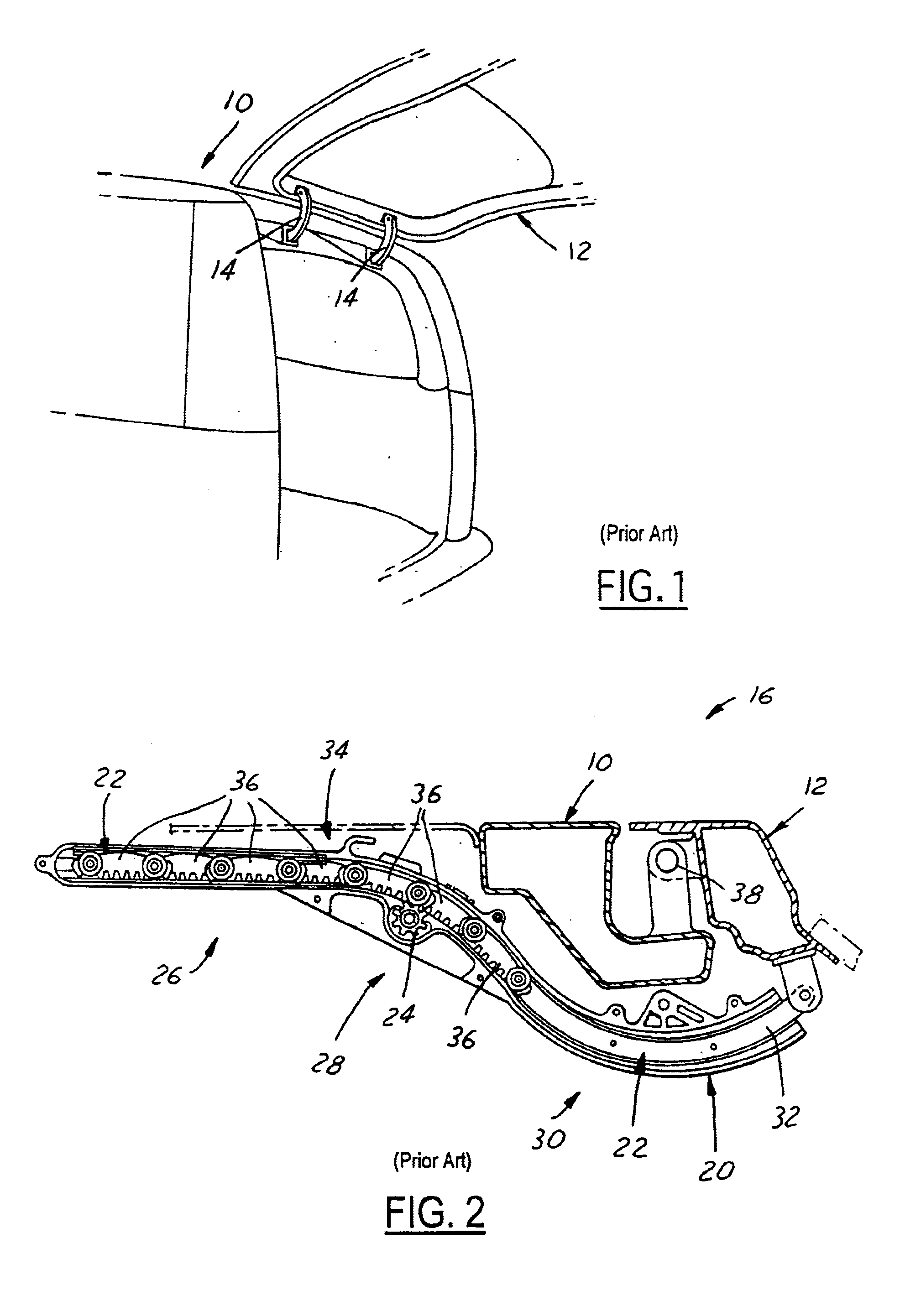
[0018]Power operated accessories for vehicles, such as power lift gates, power sliding doors, power deck lids, power swing doors, power sunroofs, etc., are becoming increasingly popular, and with their rise in popularity comes the increased need for electronic position sensors capable of tracking their position. An example of a power operated accessory is shown in U.S. Pat. No. 6,092,337 issued Jul. 25, 2000 to Johnson et al., for a Vehicle Liftgate Power Operating System, the entire contents of which are incorporated herein by reference, and is seen in FIG. 1. Referring now to FIG. 1, wherein a vehicle 10 includes a power operated liftgate 12 that is pivotally attached to the aft-end of the vehicle roof by two hinge assemblies 14. The liftgate is capable of being pivotally moved between a closed position and an open position, as seen in FIG. 1, under the power of a motor-driven drive mechanism.

[0019]Referring now to FIG. 2, the motor-driven drive mechanism previously mentioned is s...


PUM


Abstract

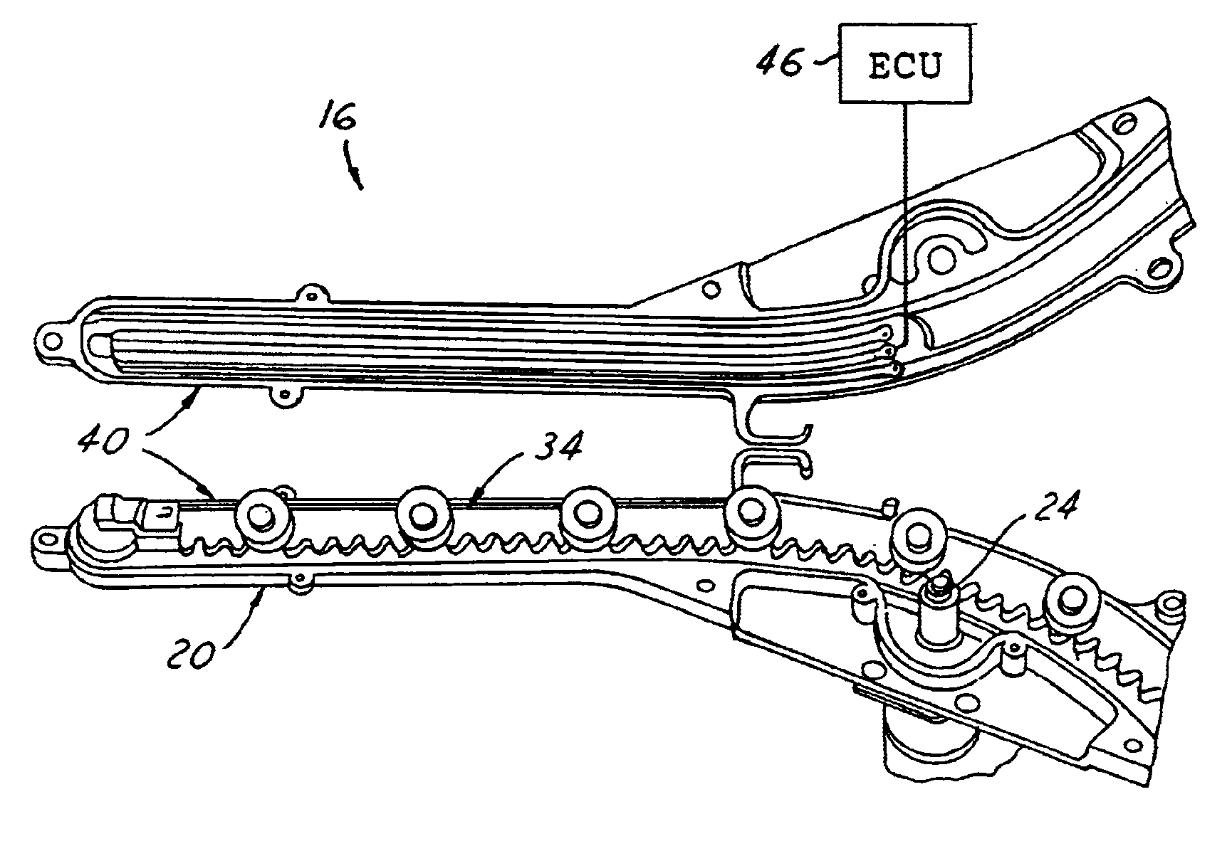
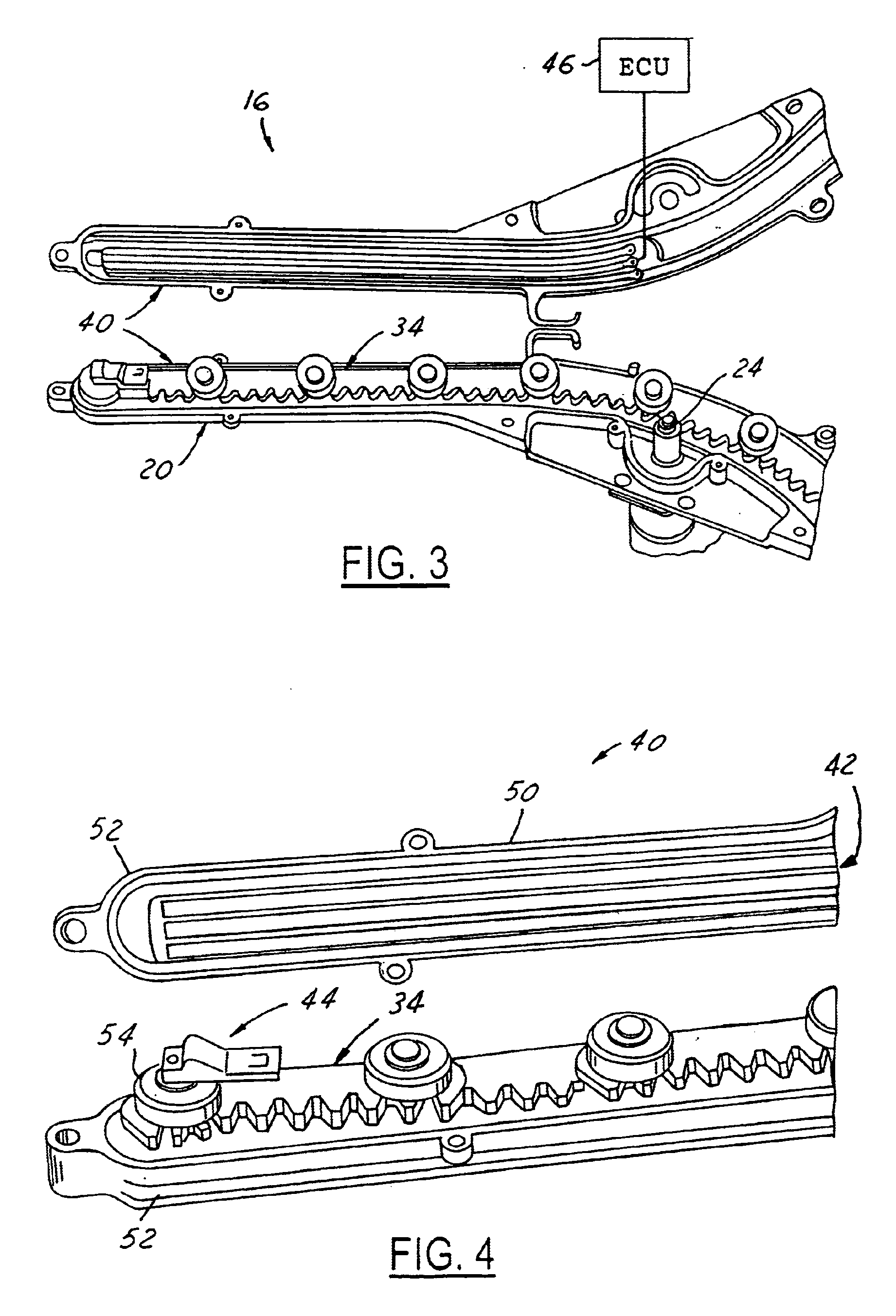
An electronic position sensor for use with a power operated vehicle accessory, such as a power liftgate. The position sensor includes an elongated resistive circuit that is mounted such that it is stationary and extends along the path of a track portion of the power operated accessory. The position sensor further includes a contact nub mounted to a link member that moves within the track portion such that the contact nub is slidingly biased against the elongated circuit. As the link member moves under the force of a motor-driven output gear, the contact nub slides along the surface of the resistive circuit, thereby affecting the overall resistance of the circuit. The position sensor uses the overall resistance to provide an electronic position signal to an ECU, wherein the signal is indicative of the absolute position of the power operated accessory. Accordingly, the electronic position sensor is capable of providing an electronic signal that enables the ECU to track the absolute position of the power operated accessory.

Description

FIELD OF THE INVENTION[0001]This invention relates generally to a position sensor for use with a power-operated accessory, and more specifically, to an electronic position sensor for use with a power operated vehicle accessory, such as a power liftgate.BACKGROUND OF THE INVENTION[0002]With the advent of power operated vehicle accessories, such as power lift gates, power sliding doors, power deck lids, power swing doors, power sunroofs, etc., comes a need for position sensors capable of tracking the position of moving components. Sensing the position of these moving components is often necessary for accomplishing other tasks, for instance, controlling the speed at which the component is driven relative to its current position, calculating the amount of time between known positions to determine if the moving component has encountered an obstacle, etc. Various techniques have been employed for monitoring the position of moving components, one of which involves sensing the position of a...

Claims


Application Information

Patent Timeline
Patent Type & Authority Patents(United States)
IPC IPC(8): E05F15/12
CPCE05F15/619E05Y2201/722E05Y2400/328E05Y2900/546E05Y2900/548E05Y2600/32E05Y2800/205E05Y2800/21E05Y2800/244E05Y2800/00
Inventor HAAG, RONALD H.CHIA, MICHAEL I.
Owner STRATTEC POWER ACCESS
Learn More