
Electronic locker system

a locker system and electronic technology, applied in the field of electronic locker systems, can solve the problems of unreasonable situation, inability to carry out fine time management, and inability to use the locker without coins

Inactive Publication Date: 2005-05-31
FULLTIME SYST
View PDF11 Cites 67 Cited by
  • Summary
  • Abstract
  • Description
  • Claims
  • Application Information

AI Technical Summary

Benefits of technology

[0009]In order to achieve the above-mentioned object, an electronic locker system according to one aspect of the present invention is provided with: a reading means for electrically reading a depositor identifier that has been preliminarily determined by a contract between a managing company of the locker and a user of the locker; an electronic lock for locking the door of the locker after luggage has been deposited in the locker; and a central control unit which, based upon the depositor identifier read by the reading means, sends information of the corresponding depositor to a locker managing center through a communication line, and when, at the time of taking out the luggage, the read depositor identifier has been identified, opens the electric lock and sends necessary information such as a luggage deposit fee to the locker managing center through the communication line, and in this arrangement, the luggage depositing process and luggage taking-out process to and from the locker are carried out based upon only the depositor identifier. Moreover, the luggage deposit fee is automatically drawn from the account of the depositor based upon the depositor identifier that has been determined by the contract between the managing company and t

Problems solved by technology

However, in the above-mentioned coin locker, since a cash payment is made by coins, it is not possible to use the locker without coins.
Moreover, since it is not possible to open the locker without the key of the locker containing the luggage, a person who has the key has to go to the site where a cabinet of the coin locker is located when the luggage is taken out.
For this reason, for example, in the case when the user who has deposited luggage in a coin locker wants another person to open the locker and receive the luggage, the user needs to pass the key to the person beforehand; this results in a troublesome task in using these coin lockers.
Moreover, in the conventional coin locker, normally, an additional fee is calculated and charged on one-day basis with 0:00 a.m. in midnight being the border; therefore, it has not been possible to carry out fine time management.
For this reason, for example, in the case when luggage is deposited at 11:55 p.m. and then taken out at 0:05 a.m., a two-day fee has to be paid for just 10 minutes' deposit of the luggage, which is an unreasonable situation.
Moreover, in the conventional coin locker, since any one can freely put and take out luggage in and from the locker, a wicked person might put a dangerous object in the locker, resulting in a problem with security in managing coin lockers.

Method used


Image

  • Electronic locker system
  • Electronic locker system
  • Electronic locker system

Examples


Embodiment Construction

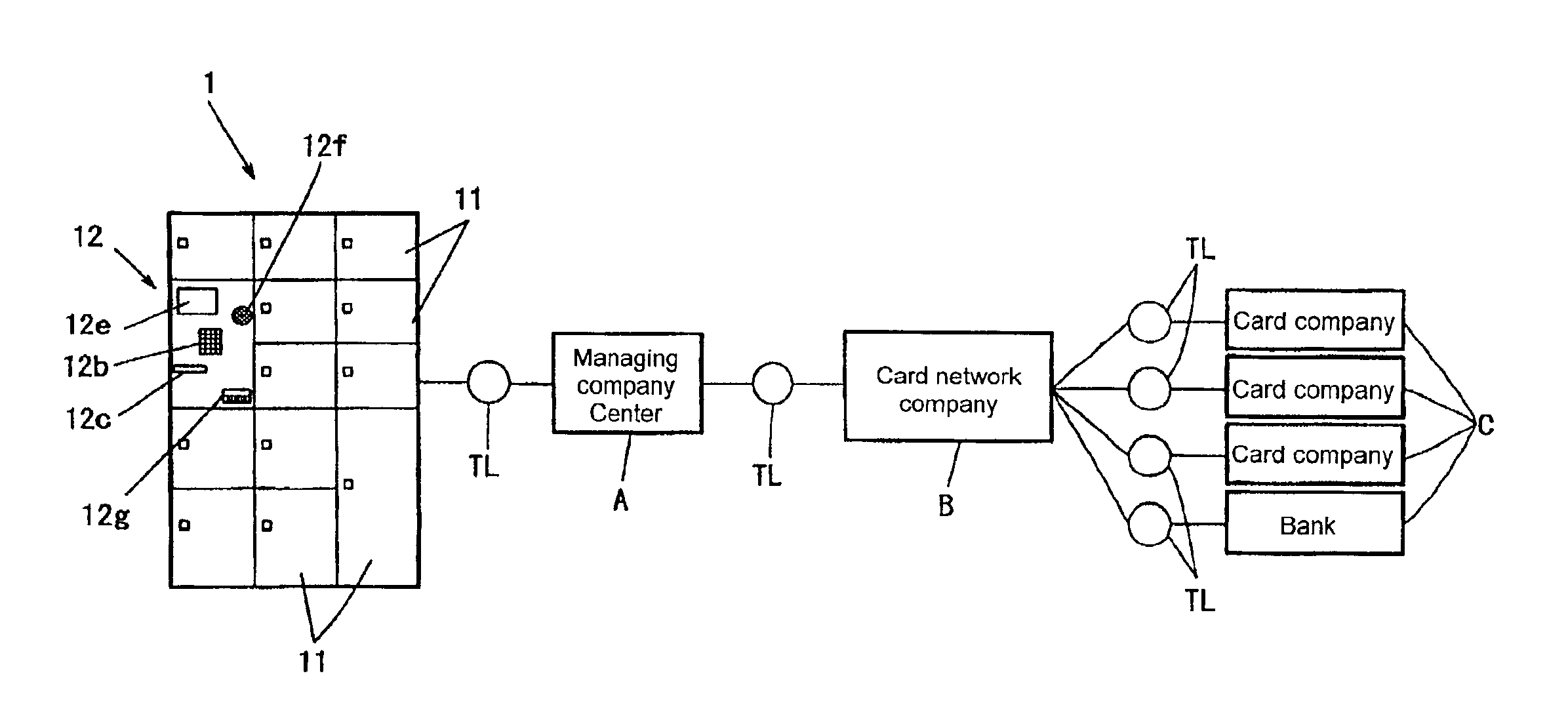
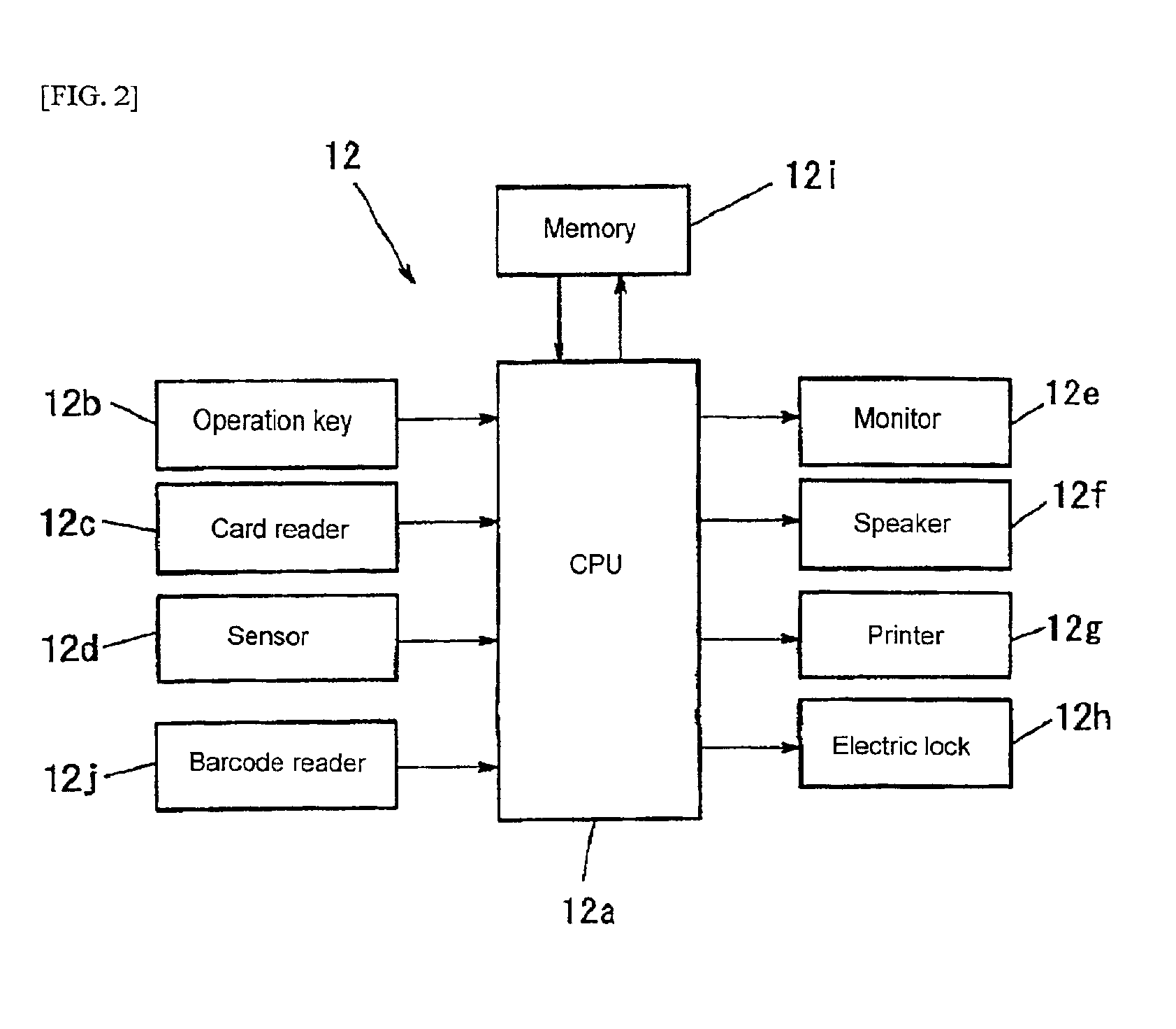
[0019]The preferred embodiments of an electronic locker system in accordance with the present invention are described below with reference to the Figures. FIGS. 1 and 2 show a first preferred embodiment of the present invention. FIG. 1 is a block diagram that shows the entire structure of an electronic locker system in accordance with the present preferred embodiment, and FIG. 2 is a block diagram showing an electrical circuit of a control box installed in the locker cabinet.

[0020]In FIG. 1, reference numeral 1 is an electronic locking type locker cabinet that is placed in a railroad station building, etc., and this locker 1 is provided with a plurality of lockers 11 having different sizes and a control box 12 which is operated by the user upon depositing and taking out luggage. This control box 12 has an arrangement shown in FIG. 2.

[0021]In other words, it is provided with a central control unit (CPU) 12a, and following parts and members are connected to the central control unit 12...


PUM


Abstract

An electronic locker system which is provided with: a locker for housing luggage; a reading means for electrically reading a depositor identifier that has been preliminarily determined by a contract between a managing company of the locker and a user of the locker; an electronic lock for locking the door of the locker after luggage has been deposited in the locker; and a central control unit which, based upon the depositor identifier read by the reading means, sends information of the corresponding depositor to a locker managing center through a communication line, and when, at the time of taking out the luggage, the read depositor identifier has been identified, releases the electric lock and sends necessary information such as a luggage deposit fee to the locker managing center through the communication line, and in this arrangement, the luggage depositing process and luggage taking-out process to and from the locker are carried out based upon only the depositor identifier. Thus, it is possible to provide an electronic locker system which can eliminate the need for any key that has been used for locking and unlocking the conventional coin locker, and automatically settle the bill for the use of the locker by using a credit card, etc., through a communication line.

Description

BACKGROUND OF THE INVENTION[0001]1. Field of the Invention[0002]The present invention relates to a locker system used for depositing luggage, placed in a station, a sleeping accommodation, or the like, and more specifically, relates to an electronic locker system which makes it possible to eliminate the need for keys used for locking and opening doors of conventional lockers, and also to automatically settle the payment of the luggage deposit fee by a credit card, etc., through a communication line.[0003]2. Description of the Related Art[0004]In a luggage depositing coin locker that has been conventionally used, luggage is deposited in an empty locker, and the door is closed, and after having put a basic fee corresponding to one-day use through a fee inserting slot attached at a locking section, the key is used for locking the locker; thus, after locking the locker, the depositor carries the key, and at the time of taking out the luggage, the depositor uses the key to open the locke...

Claims


Application Information

Patent Timeline
IPC IPC(8): G07C9/00E05B49/00E05B65/00G07F17/12
CPCG07C9/00103G06Q10/02G07C9/27
Inventor HARA, KOUICHIRO
Owner FULLTIME SYST
Features
  • Generate Ideas
  • Intellectual Property
  • Life Sciences
  • Materials
  • Tech Scout
  • Unparalleled Data Quality
  • Higher Quality Content
  • 60% Fewer Hallucinations
Learn More