RFID tag, antenna, and printer system

a printer system and antenna technology, applied in the field of printer systems, can solve the problems of increasing the need for modification of the host application software, and increasing the cost of printing

Inactive Publication Date: 2005-05-31
TSC AUTO TECH
View PDF5 Cites 174 Cited by
  • Summary
  • Abstract
  • Description
  • Claims
  • Application Information

AI Technical Summary

Benefits of technology

[0012]This allows the printer to have the capability to program data into an RFID label and verify that correct data was programmed before printing. If an error is detected, the printer can over-strike the label, indicating an error in the tag.
[0013]According to another embodiment, the RFID tag is interrogated at decreasing RF power levels until a minimum power level is determined that still allows the RFID tag to be read. This allows the system to determine a level of RFID tag performance margin or RFID tag quality level.
[0015]According to yet another embodiment of the invention, information from a data stream from a host computer is intercepted, reconfigured, and used for programming or writing to the RFID tag. In one embodiment, bar code commands are extracted from the data stream. The bar code data is then formatted into an RFID command and the bar code data is subsequently programmed into the RFID tag, and the RFID tag is printed with the commands from the data stream. The bar code data may be manipulated to ensure compliance with the RFID tag capabilities. Modifying the bar code data stream into an RFID programming command eliminates the need to modify the host application software.
[0016]It is noted that some company's thermal printers can print labels based on other company's languages allowing easy migration into competitor applications. Thus, the concept of converting the bar code command into an RFID command can be applied to a thermal printer that supports not only its standard programming language but also any competitor languages that the printer happens to support.

Problems solved by technology

Such antennas typically have large power and beam widths.
These types of antennas are not suitable for use in applications that require directional and confined interrogation.
However, printing after programming forces additional handling of the roll of labels and requires the use of additional hardware.
Furthermore, the capabilities of programming and reading RFID tags used in thermal printer labels is limited, due in part, to the mechanical profile of the printer, which may cause performance issues with radio frequency signals associated with RFID technology, and to the proximity of multiple tags coupled with the need to address (program) only one tag at a time.
If an error is detected, the printer can over-strike the label, indicating an error in the tag.

Method used


Image

  • RFID tag, antenna, and printer system
  • RFID tag, antenna, and printer system
  • RFID tag, antenna, and printer system

Examples


Embodiment Construction

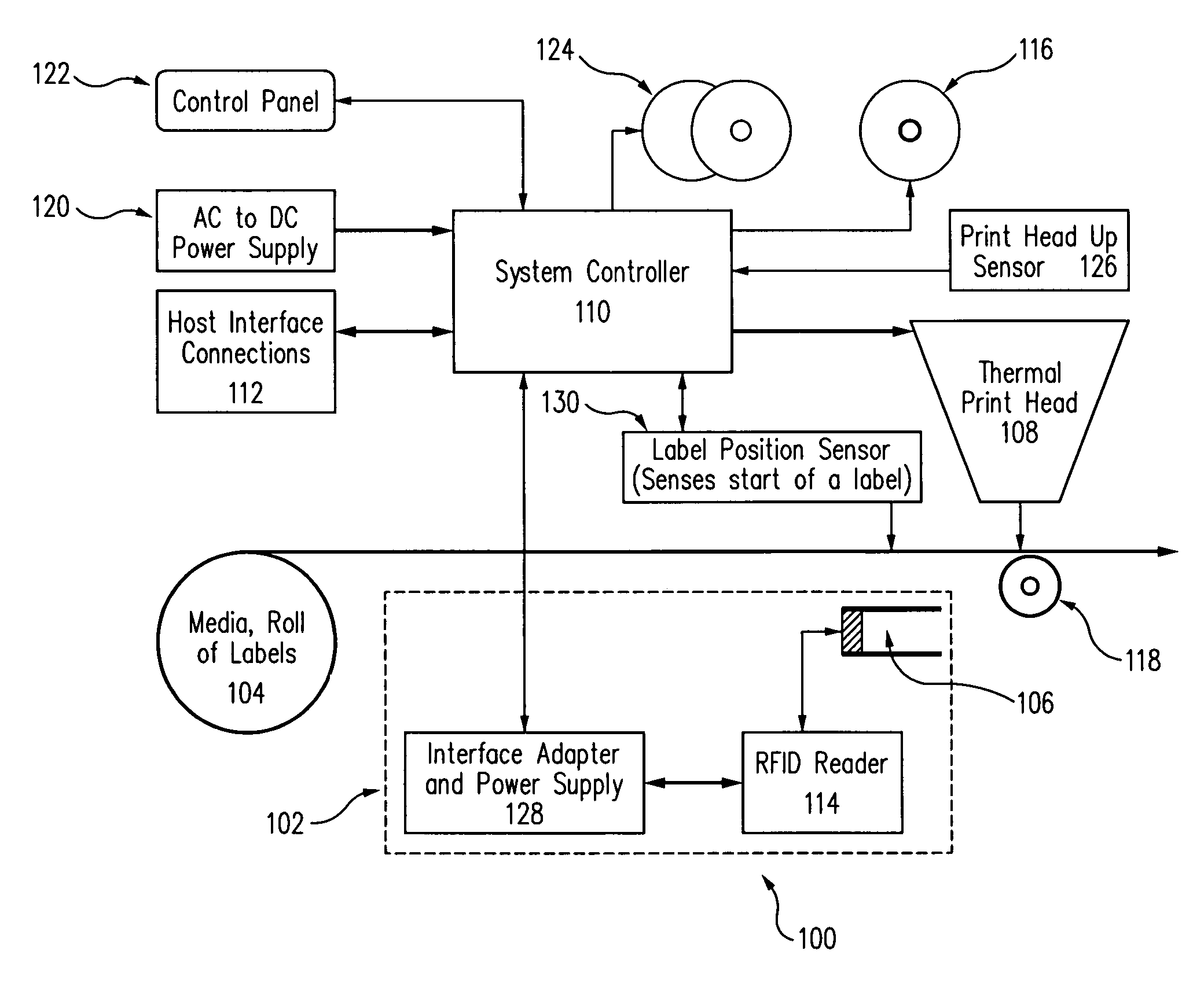
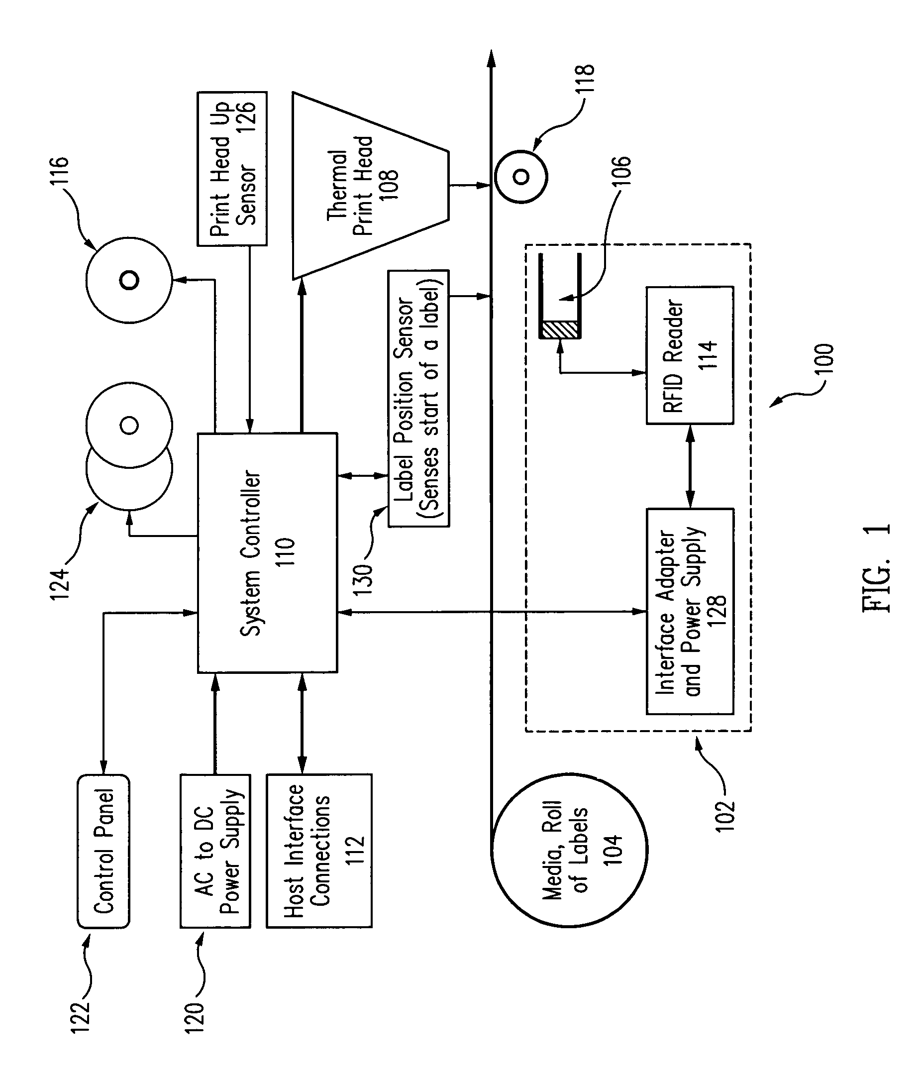
[0025]FIG. 1 shows a block diagram of a printer system 100 with a radio frequency identification (RFID) reader subsystem 102 according to one embodiment. Printer system 100 also includes a roll 104 of labels or media, where an RFID tag is embedded in each label. RFID tags are conventional passive tags available from a multitude of manufactures. One such manufacturer is Alien Technology Corporation. Labels from roll 104 are fed over an RFID antenna 106, programmed, and printed by a thermal print head 108. A host computer 112 coupled to a system controller 110 that is in turn coupled to RFID reader subsystem 102, which includes antenna 106, allows the RFID tag on each label to be written to and verified. If the RFID tag was programmed correctly, the label passes through thermal print head 108 for printing. The resulting label then has both a printed media as well as a programmed RFID tag that can be read, such as with bar code scanners and RF readers, respectively.

[0026]FIG. 2 shows a...


PUM


Abstract

An RFID label with embedded tag is passed through an RFID antenna in a printer system, where the RFID antenna allows a roll of such labels to pass in close proximity to the antenna and still allow each individual RFID tag to be read and / or programmed. The RFID antenna module is formed with a transmission line coupled to an RF phase splitter, where in one embodiment, the transmission line is formed from two parallel conductive strips.

Description

CROSS-REFERENCE TO RELATED APPLICATIONS[0001]This application is a continuation-in-part application of U.S. patent application Ser. No. 10 / 660,856, filed Sep. 12, 2003.BACKGROUND[0002]1. Field of the Invention[0003]The present invention relates to printer systems, and in particular, a printer system for communicating with radio frequency identification (RFID) labels.[0004]2. Related Art[0005]RFID transponders or tags, either active or passive, are typically used with an RFID reader to read information from the RFID tag. The information is then stored or otherwise used in various applications, such as monitoring, cataloging, and / or tracking of the item associated with the RFID tag, paying tolls, and managing security access. For example, RFID tags can be obtained through companies such as Alien Technology Corporation of Morgan Hill, Calif. Many applications for bar codes can also be used in conjunction with RFID systems.[0006]A conventional RFID tag and reader uses radio frequency si...

Claims


Application Information

Patent Timeline
Patent Type & Authority Patents(United States)
IPC IPC(8): B41J11/00B41J3/407G06K17/00B41J3/44G06K5/02G06K7/10G06K19/077
CPCB41J3/4075B41J3/44B41J11/0095G06K5/02G06K7/10346G06K17/0025G06K19/07749G06K7/10316G06K2017/0041
Inventor BARRUS, GORDON B.SCHUMAKER, RICHARD E.EDWARDS, ANDREW W.SMITH, KEVIN MARKGIBBS, DUANE C.CONCEPCION, JR., RUDY
Owner TSC AUTO TECH
Why Eureka
Try Eureka