System and Method to Reduce Standby Energy Loss in a Gas Burning Appliance and Components for Use Therewith

a technology of standby heat loss and gas burning appliances, which is applied in the direction of water supply installation, fluid pressure control, combustion process, etc., can solve the problems of more fairly inefficient appliances in energy conservation, the overall service efficiency of the appliances, and the world's environment suffering too much from problems, so as to reduce greenhouse gases, reduce standby heat loss, and operate more efficiently

Active Publication Date: 2011-07-14
INVENSYS CONTROLS AUSTRALIA
View PDF45 Cites 25 Cited by
  • Summary
  • Abstract
  • Description
  • Claims
  • Application Information

AI Technical Summary

Benefits of technology

[0017]In view of the above, embodiments of the present invention provide a new and improved standby heat loss control system that overcomes one or more of the problems exiting in the art and provides improvements over the inventors' prior system. More specifically, embodiments of the present invention provide a new and improved gas operated damper system for a hot water heater to enable hot water heaters to operate more efficiently thus reducing greenhouse gases. Preferably, embodiments of the present invention provide a new and improved gas operated damper that reduces the standby heat losses that occur as a result of thermo-syphoning of the heat from the hot water in the storage tank of a hot water heater by the flue pipe when the burner is off.

Problems solved by technology

It has now been recognized that the world's environment is suffering too much from problems caused by global climate change and greenhouse gas exposure in the atmosphere.
With such further improvement in mind, especially with the increased awareness of global climate change and changing governmental regulations, it is noted that hot water heaters, both internal and externally installed units, can be one of the more fairly inefficient appliances in energy conservation, and therefore require the burning of additional fuel to maintain the set point temperature.
One of the current disadvantages for hot water heaters is the overall service efficiency of the appliances.
Low service efficiency may be due to poor thermal efficiency of the heat into the water when the burner is on and / or excessive heat losses when the burner is off.
While a small percentage of the heat loss may be caused by poor insulation from the outside of the tank, the majority of the losses are more likely a result of excessive losses from the hot primary flue pipe (heat exchanger) in the middle of the heater.
Unfortunately, the appliance industry generally and hot water heater manufacturers specifically have been frustrated by the fact that gas operated dampers “nearly work”.
They are not popular and commonly have many problems and service issues.
One significant problem experienced by gas operated flue dampers relates to candling of the diminishing flame on shut down of conventional burners and low NOx burners.
As a result of the existence of gas in the pipe after the valve have been shut, a small flame at the injector continues to burn until the pipe is drained, which results in the gradual build up of soot in the burner.
This, in turn, often results in poor combustion, further increasing the production of greenhouse and other dangerous gasses.
Candling is especially a problem with installations where the gaseous fuel used is heavier than air such as propane, butane gas, etc.
Unfortunately, such additional plumbing and components increase the complexity and cost of such systems, as well as reducing the overall reliability of the system due to the increase in components.
In the highly cost competitive appliance industry, even with the overall lifetime cost of operation reduction and with the reduction in production of greenhouse gasses, such additional expense makes such hot water heaters undesirable by consumers.
Another problem with some gas controlled damper valves is that they can trap gas within the valving damper system.
This often results in allowing the damper only partially to close the damper, reducing the energy savings by allowing some flow therethrough.

Method used


Image

  • System and Method to Reduce Standby Energy Loss in a Gas Burning Appliance and Components for Use Therewith
  • System and Method to Reduce Standby Energy Loss in a Gas Burning Appliance and Components for Use Therewith
  • System and Method to Reduce Standby Energy Loss in a Gas Burning Appliance and Components for Use Therewith

Examples


Embodiment Construction

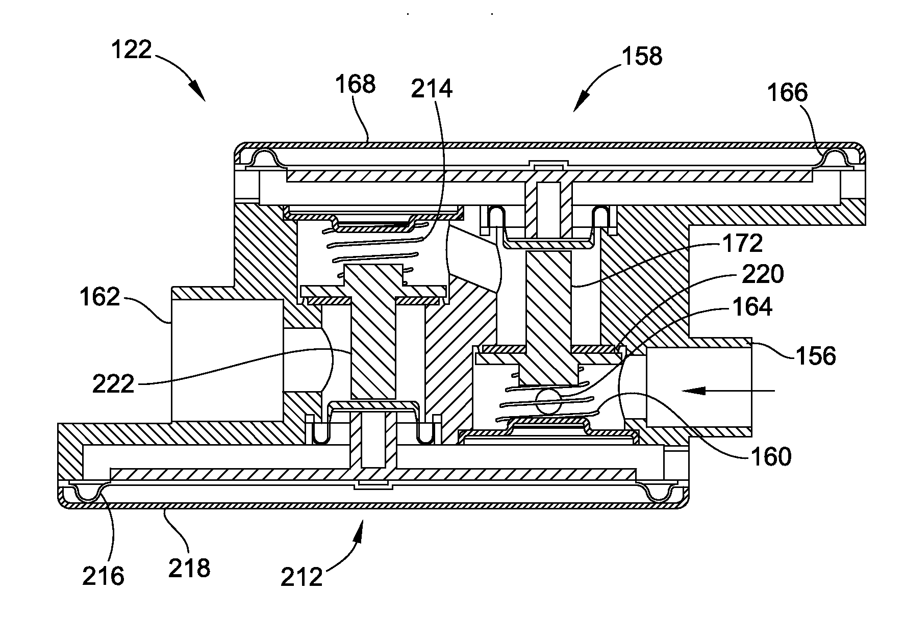
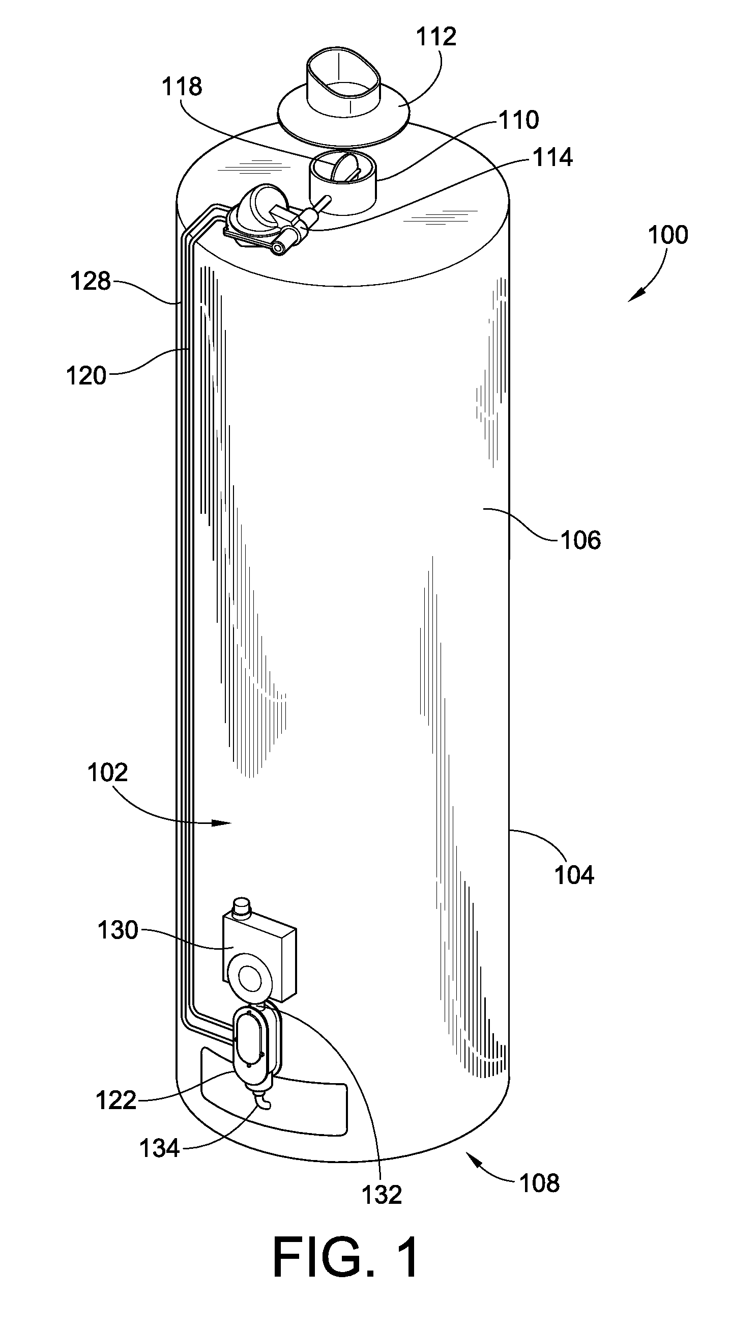
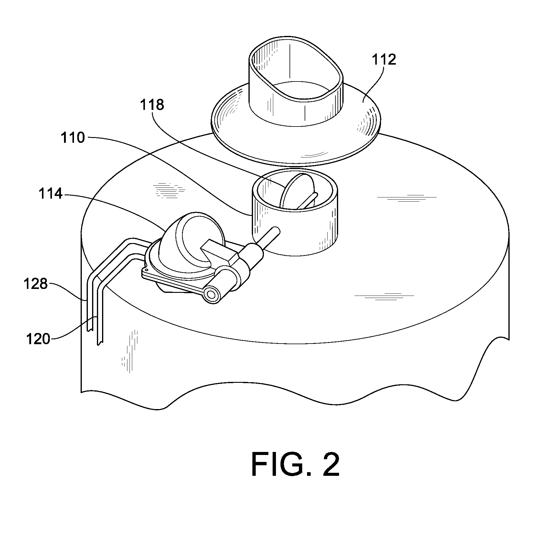
[0058]Turning now to the drawings, there is illustrated in FIG. 1 an indoor hot water heater 100 such as typically installed in dwellings in the North American market having installed thereon an embodiment of the standby heat loss control system 102 of the present invention. It should be noted that while the following description will discuss various embodiments of the present invention, such embodiments and operative environments to which these embodiments find particular applicability are provided by way of example and not by way of limitation. For example, the embodiment illustrated in FIG. 1 having the components of the standby heat loss control system 102 exposed, such as in a retrofit installation on an existing hot water heater 100, may instead in a different embodiment have one or more of such components and plumbing integrated into the combination gas controller 130 and / or housing 104 such that they are not visible to the consumer. Embodiments of the present invention may a...


PUM


Abstract

A system to reduce standby losses in a hot water heater is presented. The system utilizes a dual safety relay valve between the combination gas controller and the burner. The dual safety relay valve bypasses gas to a rotary damper actuator valve to position a damper flapper valve located over/inside the flue pipe. Once the flapper valve has opened to ensure combustion, the gas is allowed to flow back to the dual safety relay valve. Some of the bypass gas may be diverted to boost the pilot or to supply a booster. The dual safety relay valve is then opened to allow the gas supply to the burner. Once the burner is turned off, bypass gas bleeds out of the rotary damper actuator valve to close the damper flapper valve to reduce standby losses through the flue pipe, and to allow the dual safety relay valve to close tightly.

Description

FIELD OF THE INVENTION[0001]This invention generally relates to energy conservation systems, and more particularly to energy conservation systems to be employed with gas burning appliances to reduce standby losses associated therewith.BACKGROUND OF THE INVENTION[0002]It has now been recognized that the world's environment is suffering too much from problems caused by global climate change and greenhouse gas exposure in the atmosphere. To address this problem governments are now starting to adopt targets for reducing the emission of greenhouse gases to the environment and play their part to address this problem for future generations. While some countries have not adopted a firm goal, other countries, for example Australia, have adopted a policy for reducing greenhouse gases by 20% by the year 2020.[0003]Greenhouse gases can be emitted from cars, industry, farming, and households to name a few. While certainly not as apparent as a large factory with tall smokestacks, within a normal ...

Claims


Application Information

Patent Timeline
Patent Type & Authority Applications(United States)
IPC IPC(8): G05D16/06F01L3/10F16K1/16
CPCF16K1/221F16K1/443F16K31/122F23L11/005F23N2025/22F24H9/2035F23N2035/20F24H1/205F24H9/0026F24H9/0031F23N2035/18Y10T137/87917F23N2225/22F23N2235/20F23N2235/18F23L13/02F23N3/042
Inventor WHITFORD, GEOFFREY MERVYNRUWOLDT, BRENDON JOHNGACSAY, JURAJ
Owner INVENSYS CONTROLS AUSTRALIA
Why Eureka
Try Eureka