Techniques for Automatically Placing Escape Holes during Three-Dimensional Printing

a three-dimensional printing and automatic placement technology, applied in the field of computer processing, can solve the problems of inability to reuse for future use, inability to meet the requirements of printing many solid 3d objects, and inability to meet the requirements of printing, so as to facilitate comprehensive automation of hollowing flow, reduce the required design time, and reduce the amount of material or time dedicated

Active Publication Date: 2016-05-19
AUTODESK INC
View PDF1 Cites 28 Cited by
  • Summary
  • Abstract
  • Description
  • Claims
  • Application Information

AI Technical Summary

Benefits of technology

[0010]One advantage of the disclosed approach is that the automated creation of escape holes enables efficient generation of 3D models that fully leverage the capabilities of 3D printers to minimize both the printing time and material dedicated to generating 3D models. In particular, the disclosed techniques ensure compliance with escape hole constraints enforced by the 3D printer, such as a minimum number of escape holes per hollow, without relying on user-interaction. Consequently, these techniques facilitate comprehensive automation of hollowing flows, dramatically reducing the required design time compared to conventional flows that include manual, interactive steps to perforate hollow components or regions with appropriate escape holes.

Problems solved by technology

However, since the amount of material or time required to print many solid 3D objects may be unacceptable large / long, the designer often modifies the single closed 3D mesh to delineate one or more hollow components or regions.
For instance, resin-based stereolithography printers fill hollow components with uncured resin.
For instance, unprinted material that is not removed adds weight to the model, may cause post-processing visual defects (e.g. uneven dying), and is unable to be recycled for future use.
Further, many 3D printers will not print hollow components that are fully enclosed, rejecting the 3D model or printing solid components in lieu of the fully enclosed hollow components.
As is clear, such a process is time consuming, tedious, and error-prone.
Further, since automated flows are often used to generate 3D models and GUI-based modelling tools are not widely available for such flows, this GUI-based approach to adding escape holes has limited applicability.

Method used


Image

  • Techniques for Automatically Placing Escape Holes during Three-Dimensional Printing
  • Techniques for Automatically Placing Escape Holes during Three-Dimensional Printing
  • Techniques for Automatically Placing Escape Holes during Three-Dimensional Printing

Examples


Embodiment Construction

[0018]In the following description, numerous specific details are set forth to provide a more thorough understanding of the present invention. However, it will be apparent to one of skill in the art that the present invention may be practiced without one or more of these specific details.

System Overview

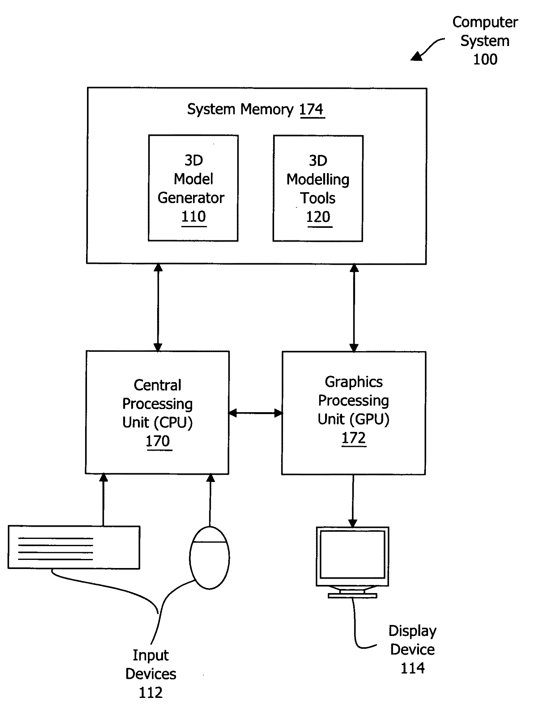
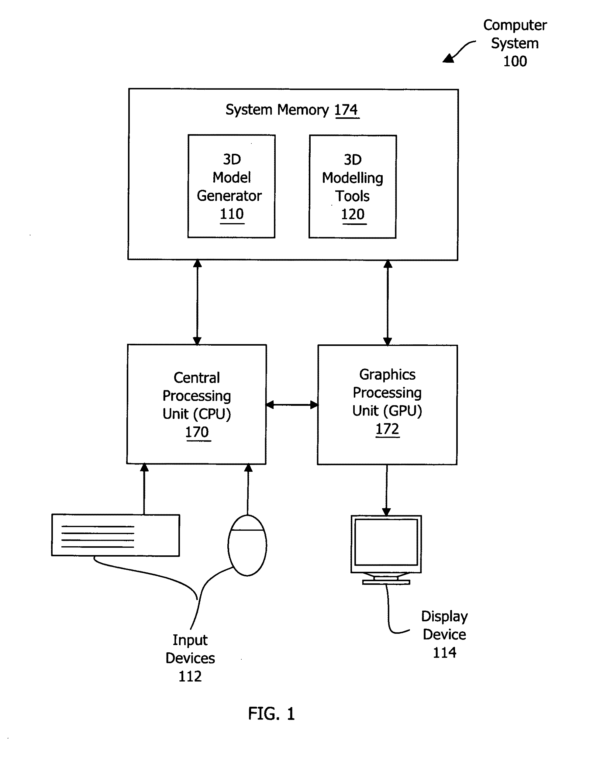
[0019]FIG. 1 is a block diagram illustrating a computer system 100 configured to implement one or more aspects of the present invention. As shown, the computer system 100 includes, without limitation, a central processing unit (CPU) 170, a system memory 174, a graphics processing unit (GPU) 172, input devices 112, and a display device 114. The CPU 170 receives input user input information from the input devices 112, such as a keyboard or a mouse. In operation, the CPU 170 is the master processor of the computer system 100, controlling and coordinating operations of other system components. In particular, the CPU 170 issues commands that control the operation of the GPU 172. The GPU 17...


PUM

PropertyMeasurementUnit
surface normalaaaaaaaaaa
diameteraaaaaaaaaa
surface areaaaaaaaaaaa

Abstract

In one embodiment of the present invention, an escape hole generator creates escapes holes designed to facilitate removal of support and/or unprinted material generated inside enclosed hollows of three-dimensional (3D) digital models during 3D printing. In operation, the escape hole generator identifies a hollow included in the three-dimensional model and then selects optimized locations for escape holes. Notably, the escape hole generator selects the locations to optimize placement heuristics, such as favoring locations closer to the bottom of the 3D model, while satisfying escape hole constraints (e.g., hole size and spacing requirements). The escape hole generator then perforates the hollow at the selected locations with geometries that provide channels from the outer surface of the hollow to the outer surface of the hollow. Advantageously, automating escape hole generation enables efficient creation of hollowed 3D models that reduce 3D printing time and material usage compared to solid 3D model counterparts.

Description

BACKGROUND OF THE INVENTION[0001]1. Field of the Invention[0002]Embodiments of the present invention relate generally to computer processing and, more specifically, to techniques for automatically placing escape holes during three-dimensional printing.[0003]2. Description of the Related Art[0004]A three-dimensional (3D) printer generates a 3D object based on a 3D printable digital model, such as a 3D mesh of triangles. Typically, a 3D printer interprets a single, closed 3D mesh as delineating a solid component of the model. However, since the amount of material or time required to print many solid 3D objects may be unacceptable large / long, the designer often modifies the single closed 3D mesh to delineate one or more hollow components or regions.[0005]To “hollow” the 3D model, the designer creates an inner shell that is separated from the single, closed 3D mesh (the outer shell) by the desired wall thickness. The 3D printer interprets the combination of inner shell and outer shell a...

Claims


Application Information

Patent Timeline
Patent Type & Authority Applications(United States)
IPC IPC(8): B29C67/00
CPCB29C67/0051B33Y10/00B29L2009/00B33Y50/00B33Y30/00B29C64/386B29C64/188
Inventor SCHMIDT, RYAN MICHAEL
Owner AUTODESK INC
Why Eureka
Try Eureka