
Rotor core lamination for a laminated rotor

a technology of laminated rotors and rotor cores, which is applied in the direction of rotors, synchronous motors, magnetic circuit shapes/forms/construction, etc., can solve the problems of additional steps to prevent the molten casting material, and achieve the elimination of expensive and laborious machining processes, and the effect of more economical and efficien

Inactive Publication Date: 2005-05-31
BRISTOL COMPRESSORS INT
View PDF30 Cites 23 Cited by
  • Summary
  • Abstract
  • Description
  • Claims
  • Application Information

AI Technical Summary

Benefits of technology

[0011]One advantage of the present invention is that a laminated rotor can be manufactured with laminations having the desired outer diameter and / or bridge thickness without the need for a subsequent machining operation.
[0012]Another advantage of the present invention is that the rotor manufacturing process is more economical and efficient because expensive and laborious machining processes are eliminated.

Problems solved by technology

One potential problem with casting the rotor bars into the laminated rotor core is that additional steps have to be taken to prevent the molten casting material, e.g. molten aluminum, from leaking or seeping between the laminations.

Method used


Image

  • Rotor core lamination for a laminated rotor
  • Rotor core lamination for a laminated rotor
  • Rotor core lamination for a laminated rotor

Examples


Embodiment Construction

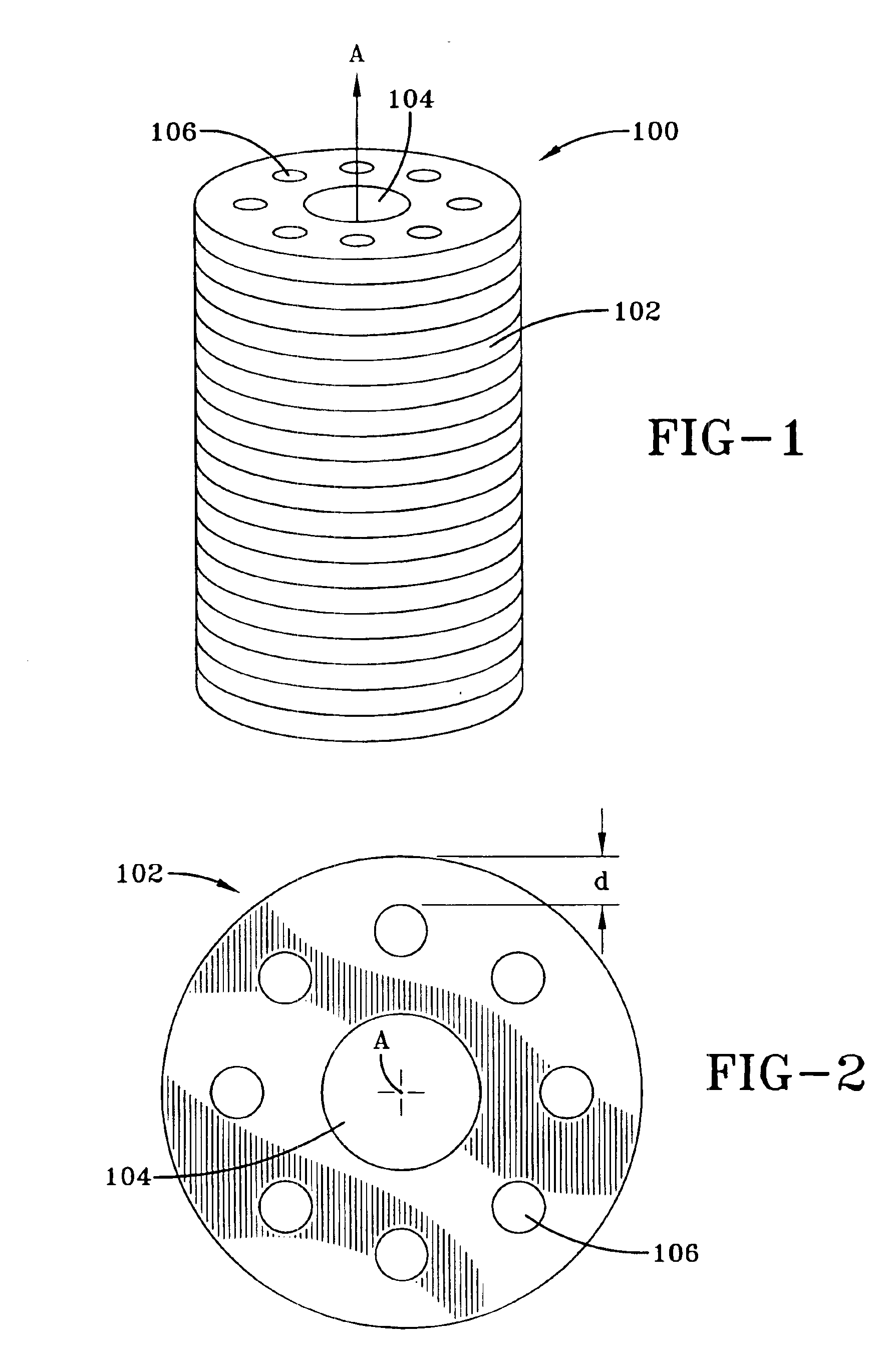
[0022]FIG. 1 illustrates a laminated rotor core 100 for use with the present invention. The laminated rotor core 100 is preferably used in a squirrel cage rotor of an induction motor for a compressor. The laminated rotor core 100 is formed or assembled by stacking a plurality of laminations 102. The number of laminations required to assemble the laminated rotor core 100 is dependent upon the thickness of the laminations 102 and the desired height of the laminated rotor core 100. In one embodiment of the present invention, the thickness of the laminations can range from about 0.015 inches to about 0.025 inches and is preferably 0.022 inches thick for a standard application and 0.018 inches thick for a “low loss” application.

[0023]FIG. 2 illustrates a top view of a lamination 102. Each lamination 102 that is assembled into the laminated rotor core 100 preferably has a central aperture or bore 104. The central bore 104 of the laminated rotor core 100 is configured to receive the shaft ...


PUM


Abstract

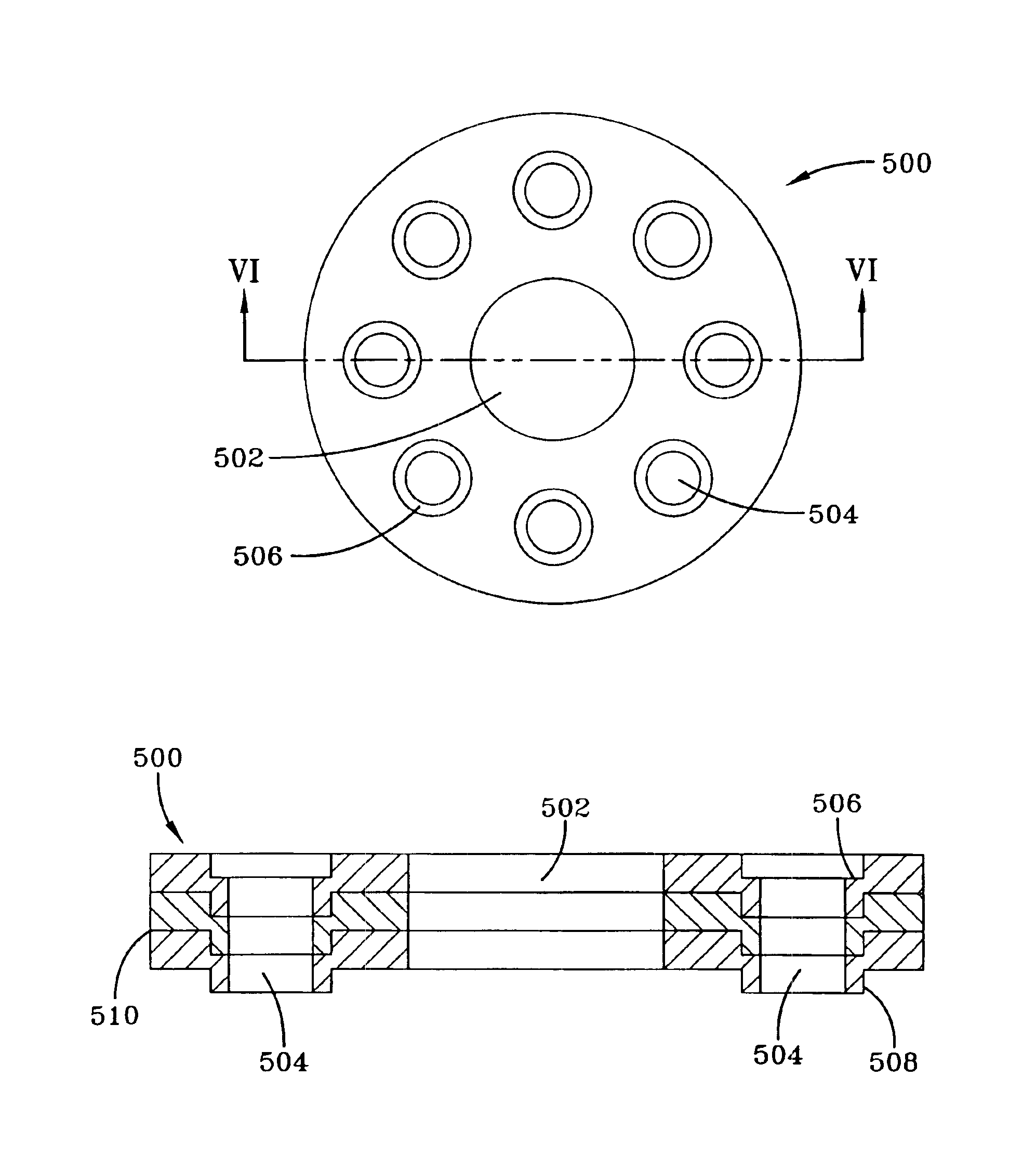
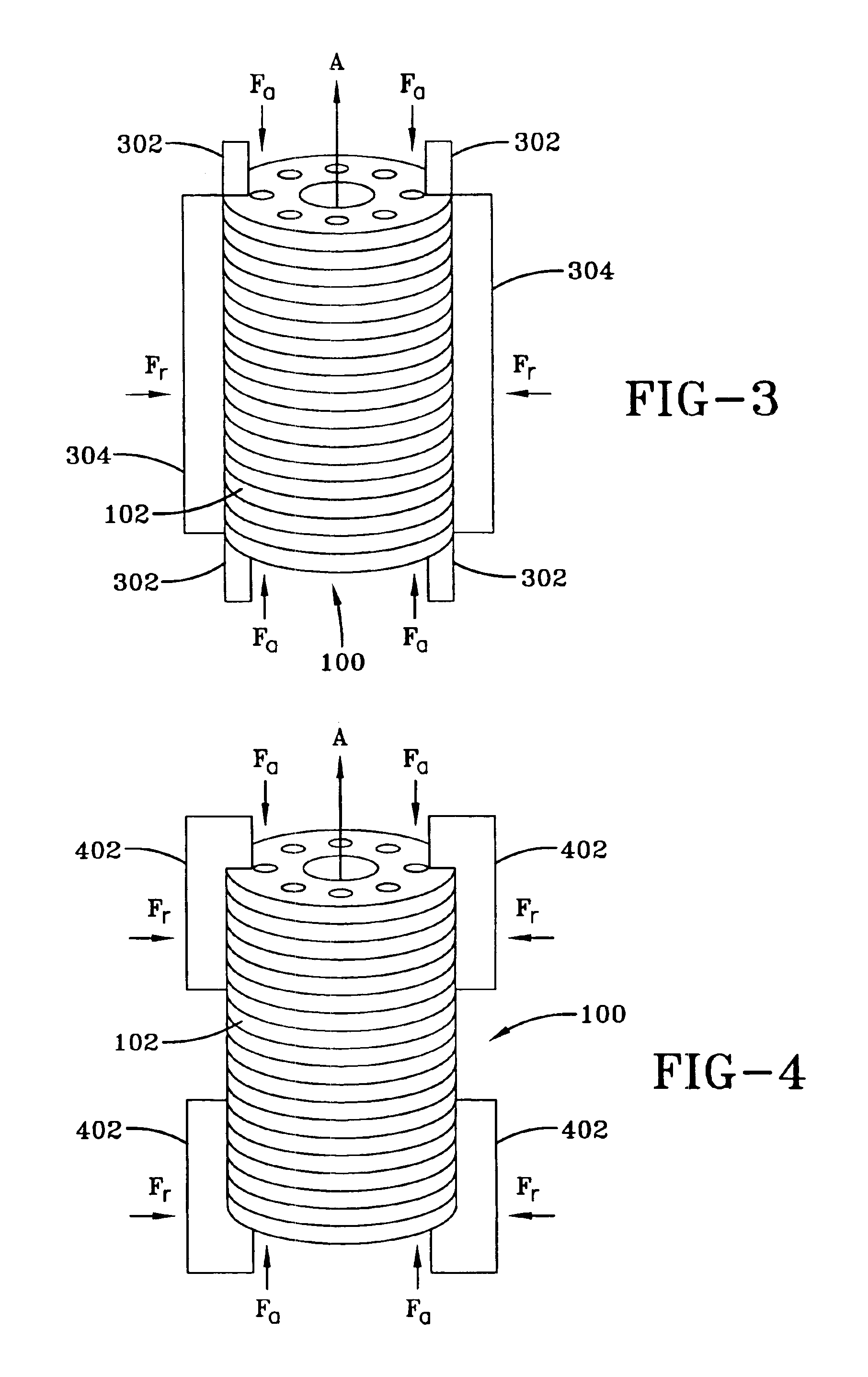
A method of assembling and manufacturing a laminated rotor is provided which uses laminations having a thin bridge thickness. Different techniques are provided for preventing the molten material used in the casting or injection molding operation from leaking or seeping between the laminations during casting. In one technique, the laminations are stacked and oriented in the conventional way, and then both axial and radial pressures are applied to the stacked laminations to hold the laminations in position for the casting process. In another technique, the laminations are formed or extruded with a lip or collar portion that fit in a countersunk portion of an adjacent lamination and forms a wall or barrier between the laminations to prevent the leakage of the molten material during the casting or injection molding operation.

Description

CROSS-REFERENCE TO RELATED APPLICATIONS[0001]This application is a divisional of application Ser. No. 10 / 440,935 filed May 19, 2003, which issued as U.S. Pat. No. 6,848,495 on Feb. 1, 2005.BACKGROUND OF THE INVENTION[0002]The present invention relates generally to a method of manufacturing a laminated rotor for a motor. More specifically, the present invention is related to methods of manufacturing a laminated rotor with laminations having a desired rotor bridge thickness prior to the assembly of the laminated rotor core.[0003]A squirrel cage rotor for use in an induction motor has a rotor core and a rotor cage that extends through the rotor core and is connected together at each end of the rotor core by end rings. The rotor core is typically made of a magnetic material such as iron or steel and the rotor cage is typically made of an electrically conductive material such as copper, aluminum or an aluminum alloy. The rotor core has a substantially cylindrical shape with a longitudina...

Claims


Application Information

Patent Timeline
Patent Type & Authority Patents(United States)
IPC IPC(8): B22D19/00
CPCB22D19/0054Y10T29/49009
Inventor EDWARDS, JERRY D.MONK, DAVID T.TOLBERT, JOHN W.
Owner BRISTOL COMPRESSORS INT
Learn More