Coil drain pan apparatus

a drain pan and coil technology, applied in the field of coil and condensate drain pan structures, can solve the problems of increasing adding to the overall cost of the air conditioning apparatus, and often affecting the operation of the condensate drain pan. the effect of standing water in the drain pan structur

Inactive Publication Date: 2005-06-07
RHEEM MFG CO
View PDF13 Cites 31 Cited by
  • Summary
  • Abstract
  • Description
  • Claims
  • Application Information

AI Technical Summary

Benefits of technology

[0007]According to one aspect of the invention, the coil drain pan is selectively positionable in horizontal and vertical air flow orientations and includes a drain structure having an outlet opening therein, and a plurality of interconnected troughs, in drainage flow communication with the outlet opening. The drain structure includes a wall area which projects downwardly beyond the interconnected troughs and is in fluid flow communication herewith, the outlet opening extending through a wall portio...

Problems solved by technology

While this general approach to coil condensate removal has long been utilized and is generally suitable for its intended purpose, it typically presents several well known problems, limitations and disadvantages.
Attachment of the auxiliary drip shield structure to the drain pan tends to be a fairly tedious procedure requiring the use of separate fasteners, and the application of a suitable sealing material at the joint between the pan and the shield.
Such fabric...

Method used


Image

  • Coil drain pan apparatus
  • Coil drain pan apparatus
  • Coil drain pan apparatus

Examples


Embodiment Construction

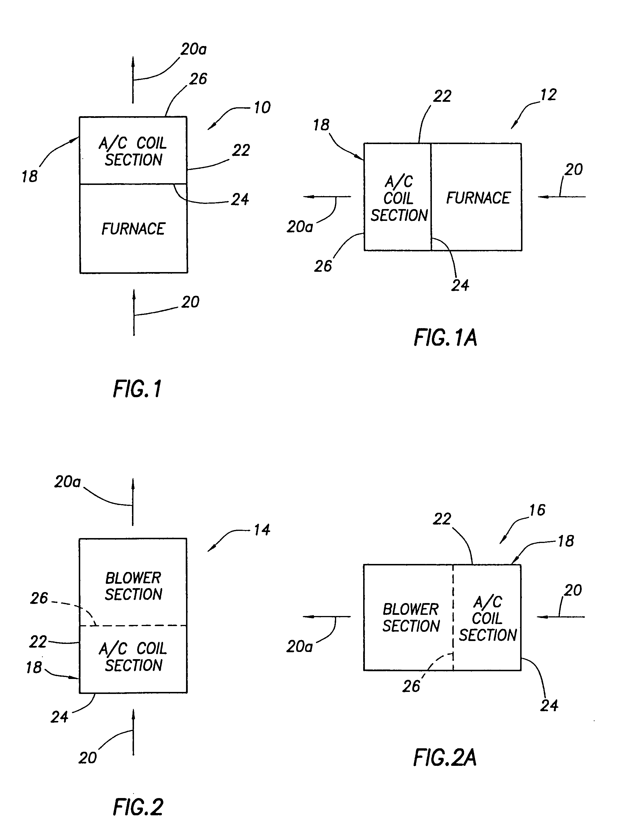
[0021]Schematically depicted in FIGS. 1–2A are four representative types of air conditioning apparatus embodying principles of the present invention—(1) a vertical air flow furnace 10 shown in FIG. 1; (2) a horizontal air flow furnace 12 shown in FIG. 1A; (3) a vertical air flow air handling unit 14 shown in FIG. 2; and (4) a horizontal air flow air handling unit 16 shown in FIG. 2A. Each of these four illustrative units incorporates therein a specially designed air conditioning coil section 18, and is operative to flow air 20 from a conditioned space therethrough, with the air exiting the unit as cooled air 20a, for return to the conditioned space, during operation of the coil section 18.

[0022]As used herein, the term “air conditioning” is intended to encompass both cooling and heating applications. Thus, while the air conditioning coil section 18 is illustratively a cooling coil section, it could alternatively be a heating coil section without departing from principles of the pres...


PUM


Abstract

An air conditioning cooling coil and its associated drain pan are positionable in either a vertical or horizontal air flow orientation. With the drain pan in its vertical air flow orientation, generally horizontally disposed drainage trough portions of the drain pan around its periphery are sloped relative to one another in a manner such that all coil condensation received in the troughs flows by gravity therethrough into a downwardly projecting condensate well and outwardly through an outlet opening therein. When the drain pan is in its horizontal air flow orientation, the troughs are disposed generally in a vertical plane, and coil condensation falls on a specially designed horizontal drip shield, which may be connected to the pan without tools, separate fasteners or sealing material, and drains along the drip shield into one of the pan troughs for discharge from the main drain opening of the pan.

Description

BACKGROUND OF THE INVENTION[0001]The present invention generally relates to air conditioning apparatus and, in representatively illustrated embodiments thereof, more particularly relates to condensate drain pan structures used in conjunction with air conditioning cooling coils.[0002]A coil used in air conditioning apparatus such as furnaces, air handling units, and heat pumps extracts moisture from the air which is being flowed externally across the coil (by a blower portion of the apparatus) and cooled by the coil for delivery to a conditioned space served by the apparatus. This moisture extraction creates condensation (water) on the exterior of the coil which drips from the coil into an associated drain pan structure within the air conditioning apparatus. Coil condensation dripping into the pan flows away therefrom by gravity via a condensate drain line suitably connected to the pan. While this general approach to coil condensate removal has long been utilized and is generally sui...

Claims


Application Information

Patent Timeline
IPC IPC(8): F24F1/00F24F13/22F24F13/00F24F1/0007
CPCF24F13/222F24F1/0007
Inventor JIN, CHANGJIANGBROWN, PHILLIP GUYBERGT, CARL
Owner RHEEM MFG CO
Why Eureka
Try Eureka