Lock open and control system access apparatus and method for a downhole safety valve

a technology of control system and access apparatus, which is applied in the direction of fluid removal, borehole/well accessories, construction, etc., can solve the problems of high gas flow rate, complicated and expensive manufacturing of tools, and potential design challenges

Inactive Publication Date: 2005-06-07
BAKER HUGHES INC
View PDF17 Cites 67 Cited by
  • Summary
  • Abstract
  • Description
  • Claims
  • Application Information

AI Technical Summary

Benefits of technology

[0010]A lock open device for a flapper is disclosed. The tool engages in the sub-surface safety valve (SSSV) body and rotates the flapper to the open position, without shifting the flow tube. The flapper base is preferably held by a shearable thread and has a groove for engagement by the tool. The tool jars down on the flapper base to shear the thread and force the held open flapper into a retaining groove. Optionally, a penetrating tool can be connected so that, in a single trip, the flapper can be locked open and the pressurized control system can be accessed. Shearing the thread allows the flow tube spring to bias the held open flapper into its retaining groove.

Problems solved by technology

One was that the band could become dislodged under high gas flow rates.
The tool was complicated and expensive to manufacture.
The expanding ring presented design challenges and required stocking a large variety to accommodate different conditions.
The disadvantages were that the flow tube was permanently damaged and that the flow tube had to be forced against a closure spring force before being dimpled to hold that position.
This made disassembly of the SSSV with the flow tube under spring pressure a potentially dangerous proposition when the valve was later brought to the surface.
This design had the safety issues of disassembly at the surface where the flow tube was under a considerable spring force.
Additionally, fluid communication into the control system was not an option when locking open using this tool.
This system has the risk of a flow tube under a spring force causing injury when later disassembled at the surface.
Finally, the tool is fluid pressure actuated, which will require a long fluid column to eventually communicate with the formation, a particular disadvantage in gas wells.

Method used


Image

  • Lock open and control system access apparatus and method for a downhole safety valve
  • Lock open and control system access apparatus and method for a downhole safety valve
  • Lock open and control system access apparatus and method for a downhole safety valve

Examples


Embodiment Construction

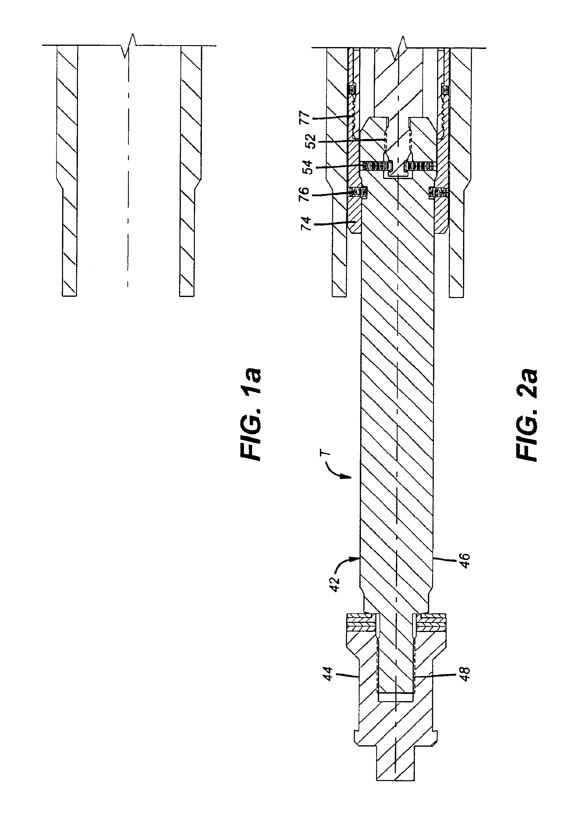
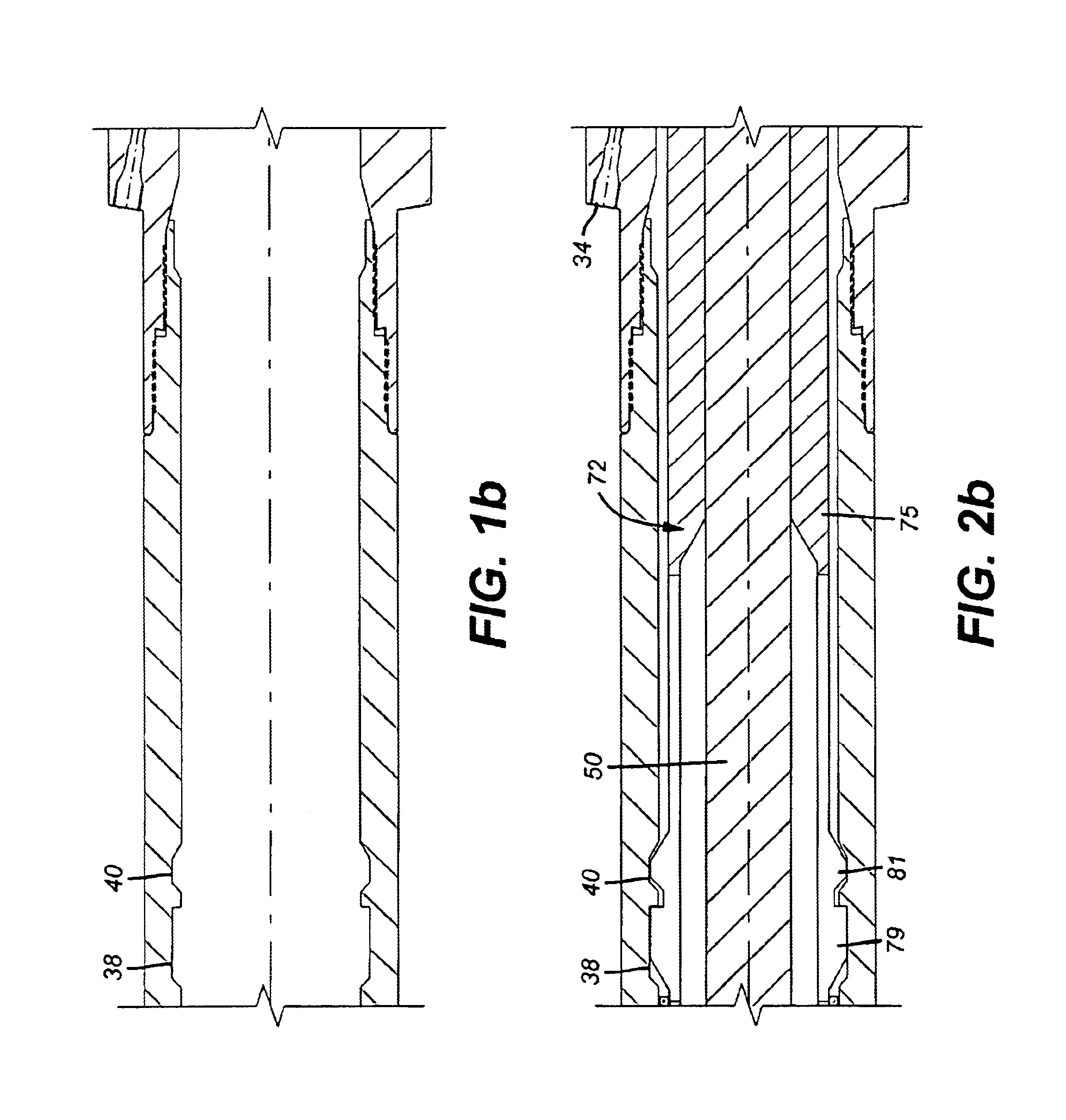
[0022]The sub-surface safety valve is illustrated in the closed position for the flapper 12, in FIG. 1. Spring 16 bearing on shoulder 18 biases the flow tube 14 upwardly. Flapper 12 is secured to flapper base 20 at pivot 22. Spring 24 biases flapper 12 to the closed position shown in FIG. 1d. Flapper base 20 is secured by sleeve 26 to body 28. That connection is preferably by a thread 30. Thread 30 is designed to release under a predetermined force applied to flapper base 20. Other retainers that selectively release such as shear pins or collets can be used instead of thread 30 as contemplated in alternative forms of the present invention. A piston 32 sees pressure from a control line extending from the surface (not shown) and connected to port 34. Piston 32 engages groove 36 to push the flow tube 14 down against the force of spring 16. Grooves 38 and 40 are for locating the lock open tool T as shown in FIG. 2b. FIG. 1d shows an enlargement of the area around thread 30.

[0023]FIGS. 2...


PUM


Abstract

A lock open device for a flapper is disclosed. The tool engages in the sub-surface safety valve (SSSV) body and rotates the flapper to the open position, without shifting the flow tube. The flapper base is preferably held by a shearable thread and has a groove for engagement by the tool. The tool jars down on the flapper base to shear the thread and force the held open flapper into a retaining groove. Optionally, a penetrating tool can be connected so that, in a single trip, the flapper can be locked open and the pressurized control system can be accessed. Shearing the thread allows the flow tube spring to bias the held open flapper into its retaining groove.

Description

FIELD OF THE INVENTION[0001]The field of this invention is lock open devices for sub-surface safety valves (SSSV) and related techniques for gaining access to the pressurized control system for subsequent operation of an inserted replacement.BACKGROUND OF THE INVENTION[0002]SSSVs are normally closed valves that prevent blowouts if the surface safety equipment fails. Conditions can arise where the SSSV fails to function for a variety of reasons. One solution to this situation has been to lock open the SSSV and to gain access into the pressurized control system that is used to move the flow tube to push the flapper into an open position against the force of a closure spring that urges the valve into a closed position. Thereafter, a replacement valve is delivered, normally on wireline, and latched into place such that the newly formed access to the control system of the original valve is now straddled by the replacement valve. This allows the original control system to be used to opera...

Claims


Application Information

Patent Timeline
Patent Type & Authority Patents(United States)
IPC IPC(8): E21B29/08E21B34/00E21B34/10E21B34/14
CPCE21B29/08E21B34/102E21B34/106E21B34/14E21B2200/05E21B34/10
Inventor MYERLEY, THOMAS S.STRATTAN, SCOTT C.MCVICKER, VAN J.
Owner BAKER HUGHES INC
Why Eureka
Try Eureka