Refined illuminating lamp structure

a technology of illuminating lamps and lampshades, applied in lighting support devices, lighting and heating apparatuses, and ways, etc., can solve the problems of not having a good design, consuming multiple power sockets, and the prior art described above still has some defects, and achieves the effect of refined illuminating

Inactive Publication Date: 2005-06-07
LAI LI CHUN
View PDF6 Cites 80 Cited by
  • Summary
  • Abstract
  • Description
  • Claims
  • Application Information

AI Technical Summary

Benefits of technology

[0008]An object of the present invention is to provide a refined illuminating lamp structure which does not need to set any power socket.
[0009]Another object of the present invention is to provide a refined illuminating lamp structure which can make multiple illuminating lamps to produce light at the same time only through employing an extended conducting wire.
[0010]Another further object of the present invention is to provide a refined illuminating lamp structure which can be plugged in the outdoor lawn and the illuminating angle thereof also can be adjusted, so that it can increase the sensing beauty of the gardens and buildings.

Problems solved by technology

However, although the illuminating lamp can intersperse the night to be so beautiful, in the prior art, one illuminating lamp has to equip with one set of power conducting wires.
That means when multiple illuminating lamps are under using, it has to consume multiple power sockets.
Thus, it can be seen, the prior art described above still has some defects, is not a good design, however, and is urgently to be improved.
Because of the technical defects of described above, the applicant keeps on carving unflaggingly to develop a refined illuminating lamp structure through wholehearted experience and research.

Method used


Image

  • Refined illuminating lamp structure
  • Refined illuminating lamp structure
  • Refined illuminating lamp structure

Examples


Embodiment Construction

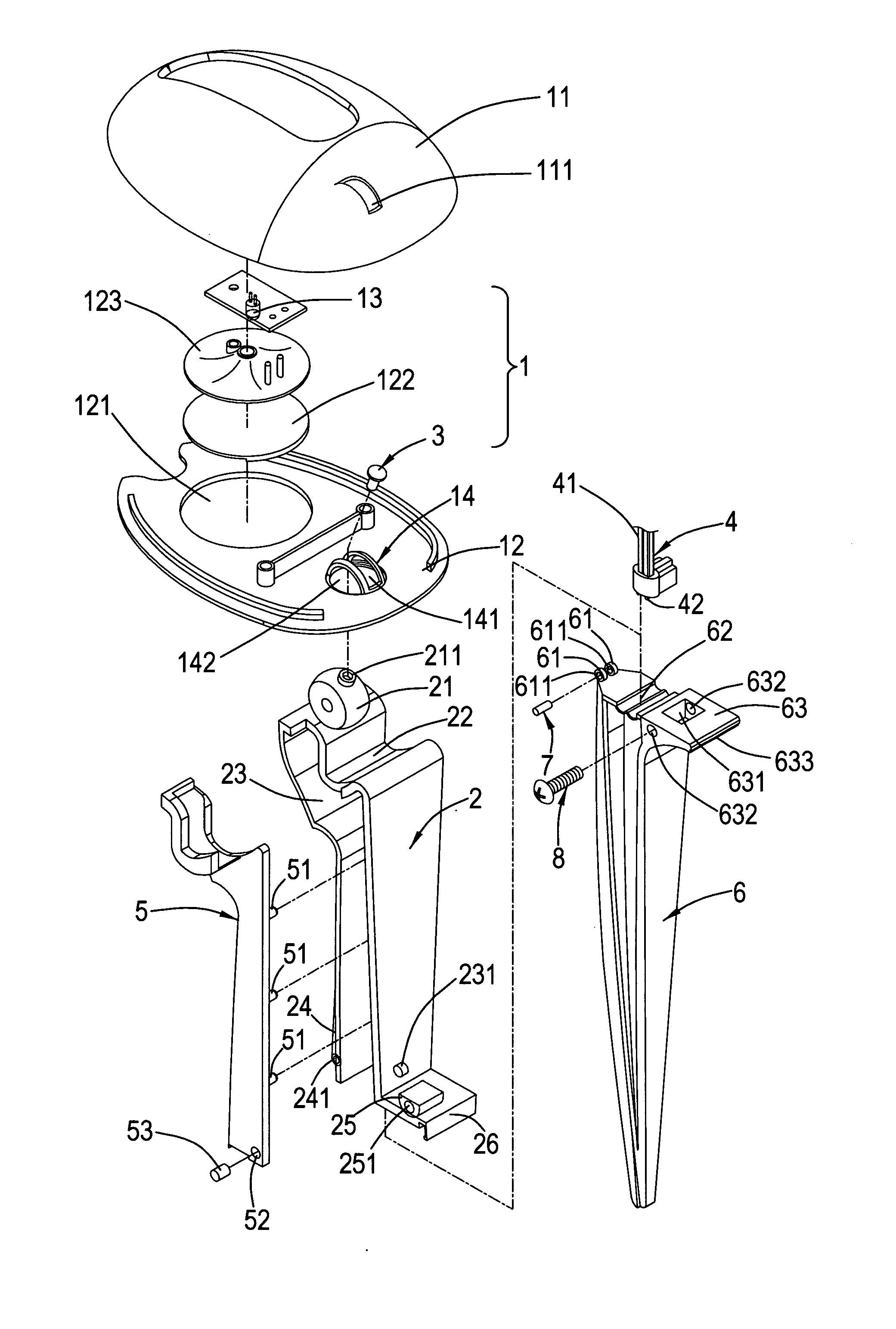
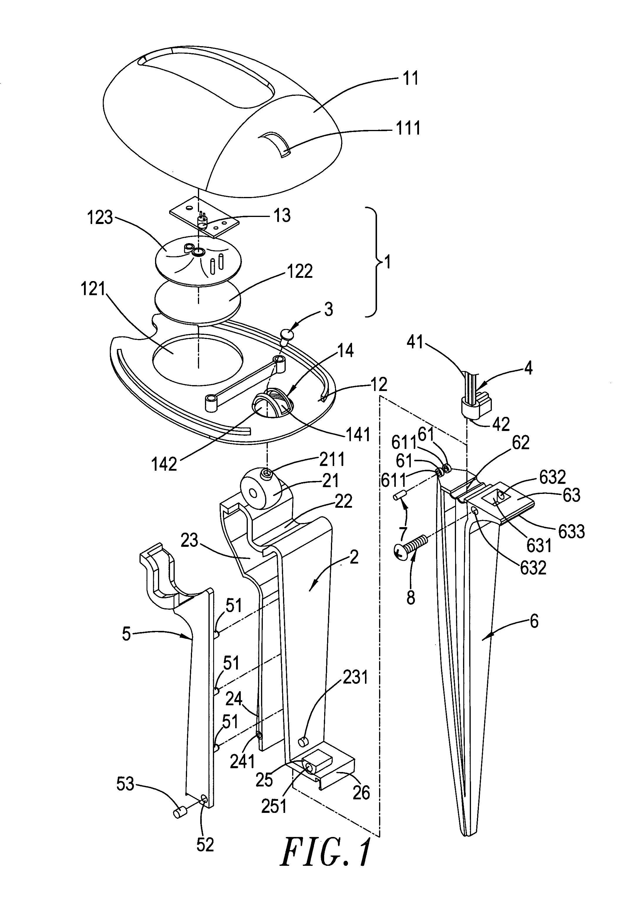
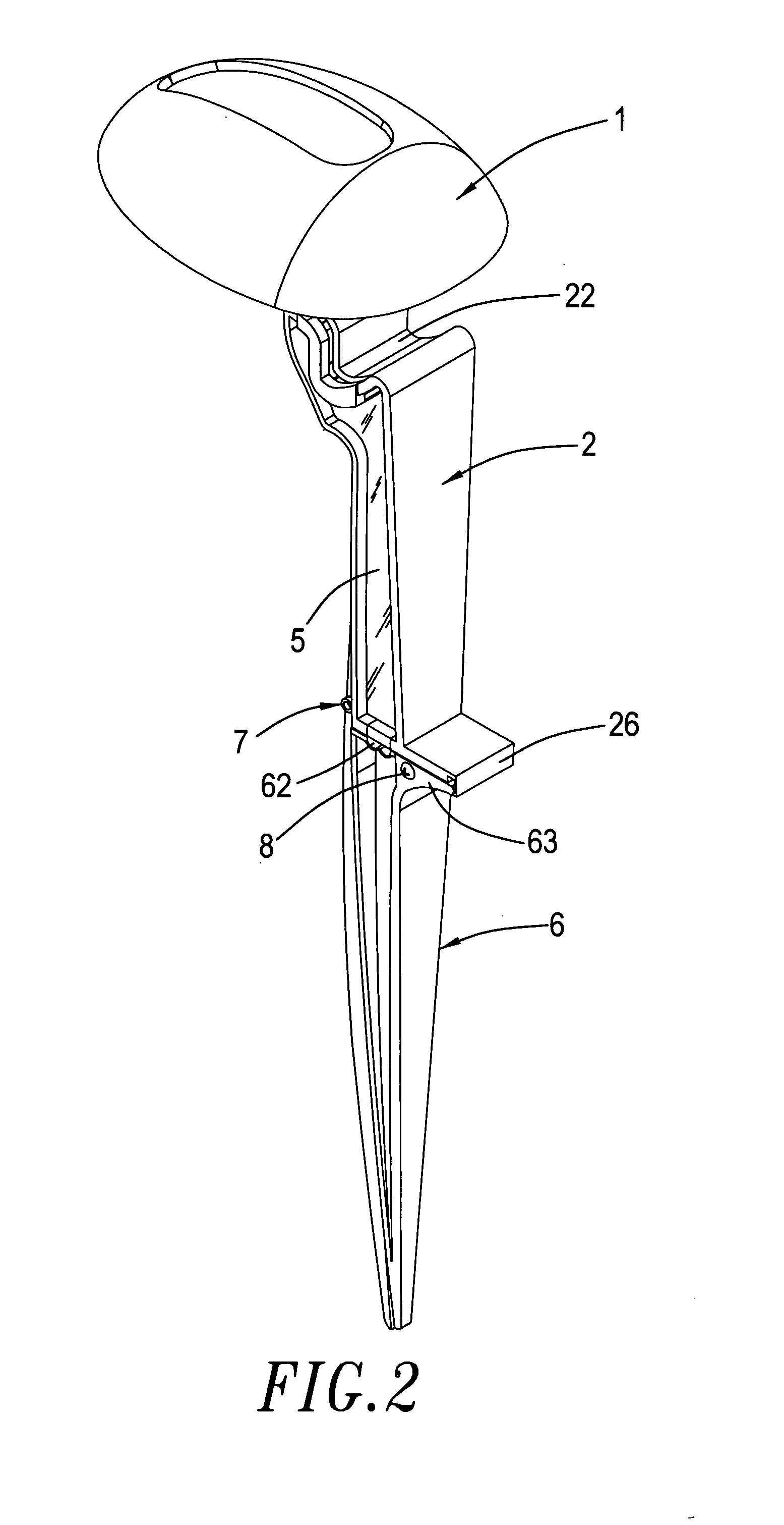
[0020]Please refer to FIGS. 1–3 which illustrate a refined illuminating lamp structure according to the present invention. The refined illuminating lamp structure mainly includes:[0021]a lamp case 1 constructed by a upper case 11 and a lower case 12, wherein the lower case 12 has a hole 121 set at a central portion thereof, in which the hole 121 is sequentially connected with a lampshade 122 and a socket 123 having an illuminator 13 mounted therein, the lower case 12 has a connecting portion 14 downwardly extending from an end terminal thereof, in which the connecting portion 14 includes an arc conducting-opening 141 and an opening 142 set at one side of the arc conducting-opening 141, and the upper case 11 has an arc conducting-trough 111 set thereon at a position corresponding to the arc conducting-opening 141 on the connecting portion 14 of the lower case 12;[0022]a holder 2 having a pivot-connecting portion 21 mounted on a top end thereof, in which the pivot-connecting portion 2...


PUM


Abstract

A refined illuminating lamp structure is disclosed. A lamp case is pivotally connected to a top surface of the holder so as to reverse on the top surface of a holder. The bottom surface of the holder is connected with a taper body. The top surface of the taper body has a wire-fixing opening mounted thereon and a power conducting element is set at the connecting plane of the holder and the taper body. The power conducting element has one end which is a conducting wire and the other end exposed to have an awl conducting piece. The conducting piece is placed in the wire-fixing opening and the conducting wire connects with the illuminator inside the lamp case along the side of the holder. Several illuminating lamps are simultaneously plugged in the outdoor lawn and a long conducting wire having a power socket is placed in the power fixing opening at the top surface of the taper body. When the holder and the taper body are connected together, the conducting pieces of the power conducting element will immediately penetrate through the insulating layer of the long conducting wire and contact with the copper wire so that the illuminator inside the lamp can produce light for achieving the purpose of illuminating.

Description

BACKGROUND OF THE INVENTION[0001]1. Field of the Invention[0002]The present invention relates to a refined illuminating lamp structure, and more particular to a refined illuminating lamp structure which can make multiple illuminating lamps to produce light at the same time only through one long conducting wire.[0003]2. Description of the Prior Art[0004]The illuminating lamp is really an important electric equipment for people nowadays. In addition to providing an illumination for dark, it also can present a beautiful and touching visual effect at night for buildings, flowers and plants, and trees so as to clear off the tiredness accumulated all the day.[0005]However, although the illuminating lamp can intersperse the night to be so beautiful, in the prior art, one illuminating lamp has to equip with one set of power conducting wires. That means when multiple illuminating lamps are under using, it has to consume multiple power sockets. Once the power sockets are insufficient, the num...

Claims


Application Information

Patent Timeline
Patent Type & Authority Patents(United States)
IPC IPC(8): F21V21/30F21V21/14F21S8/08F21S8/00F21V17/00F21V17/10F21V21/002F21V27/00
CPCF21S8/081F21V17/107F21V21/002F21V21/30F21V21/0824F21W2131/109F21V27/00F21W2131/10
Inventor LAI, LI-CHUN
Owner LAI LI CHUN
Why Eureka
Try Eureka