Switch device having good sense of operational touch even when sliding operating knob or rocking operating knob is attached thereto

a technology of operating knob and operating knob, which is applied in the direction of switches with three operating positions, switches with two operating positions, contact mechanisms, etc., can solve the problems of irregularity or saccade, and rarely obtain good operational touch, so as to facilitate the addition of different operational performances and improve the sense of operation. touch, the effect of smooth rotation

Active Publication Date: 2005-06-07
ALPS ALPINE CO LTD
View PDF10 Cites 16 Cited by
  • Summary
  • Abstract
  • Description
  • Claims
  • Application Information

AI Technical Summary

Benefits of technology

[0009]The present invention has been made in consideration of the above problems, and an object of the present invention is to provide a switch device which makes it possible to give an operator a good sense of operational touch even if the switch device is combined with an operating knob that is rockably operated or slidably operated.
[0014]In the above-mentioned switch device, preferably, the driving bodies are respectively provided with driving arm parts that protrude laterally from the case. In this case, for example, a construction can be realized in which the driving arm parts are disposed above push switches juxtaposed in the vicinity of the case and the driving bodies are driven to rotate via the pressed parts, such that the driving arm parts operate to press the push switches. Therefore, even if the number of operating knobs is not increased or the shape thereof is not complicated, it is possible to easily add different operational performances by using the switch device.
[0015]The present invention relates to a switch device in which the driving body is driven to rotate such that the conductor plate is brought into contact with or separated from the fixed contact members. In case rocking operation or sliding operation of the operating knob is carried out, an angular moment that tends to flex the plate spring member is not applied to the driving body, but the driving means can be smoothly driven to rotate. As a result, a good sense of operational touch can usually be obtained.

Problems solved by technology

This may increase sliding resistance partially and undesirably and result in the sense of irregularity or saccade.
Therefore, a problem occurs in that a good sense of operational touch is rarely obtained.

Method used


Image

  • Switch device having good sense of operational touch even when sliding operating knob or rocking operating knob is attached thereto
  • Switch device having good sense of operational touch even when sliding operating knob or rocking operating knob is attached thereto
  • Switch device having good sense of operational touch even when sliding operating knob or rocking operating knob is attached thereto

Examples


Embodiment Construction

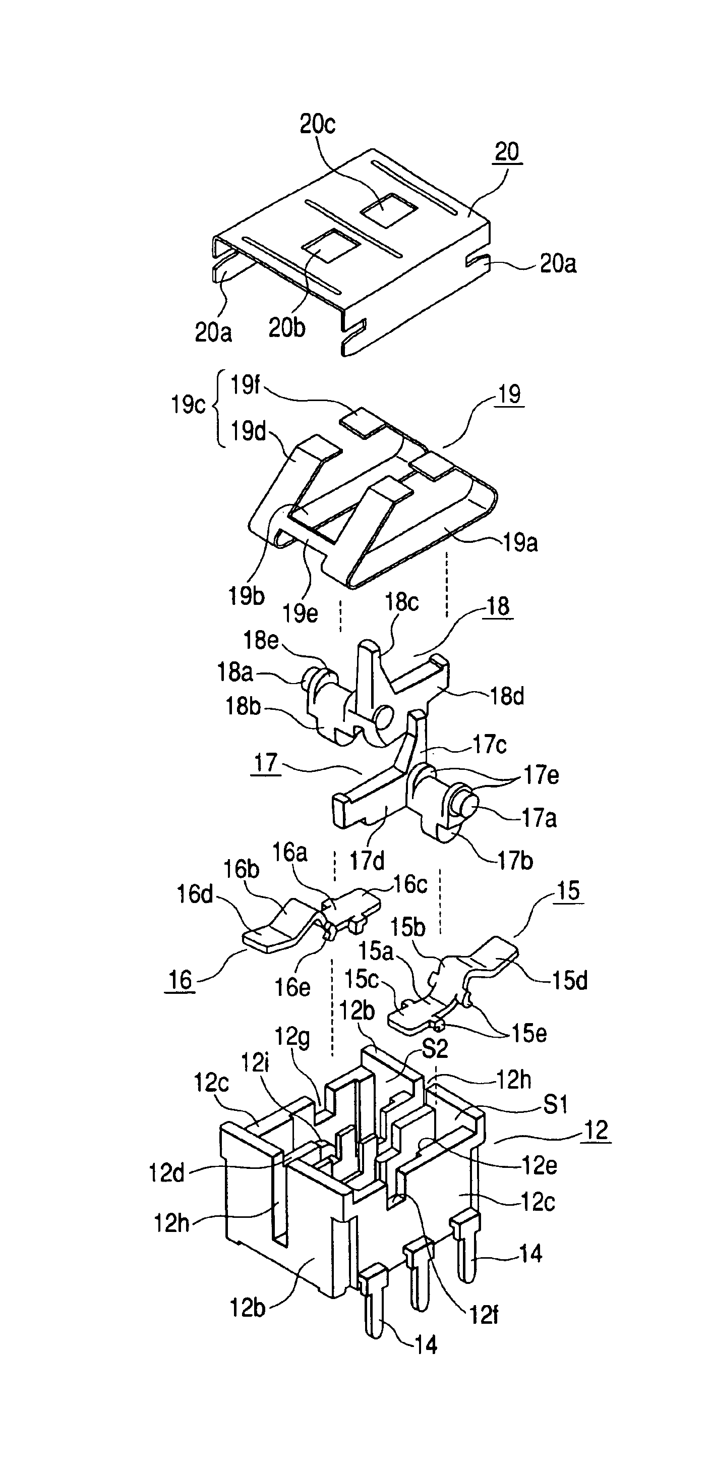
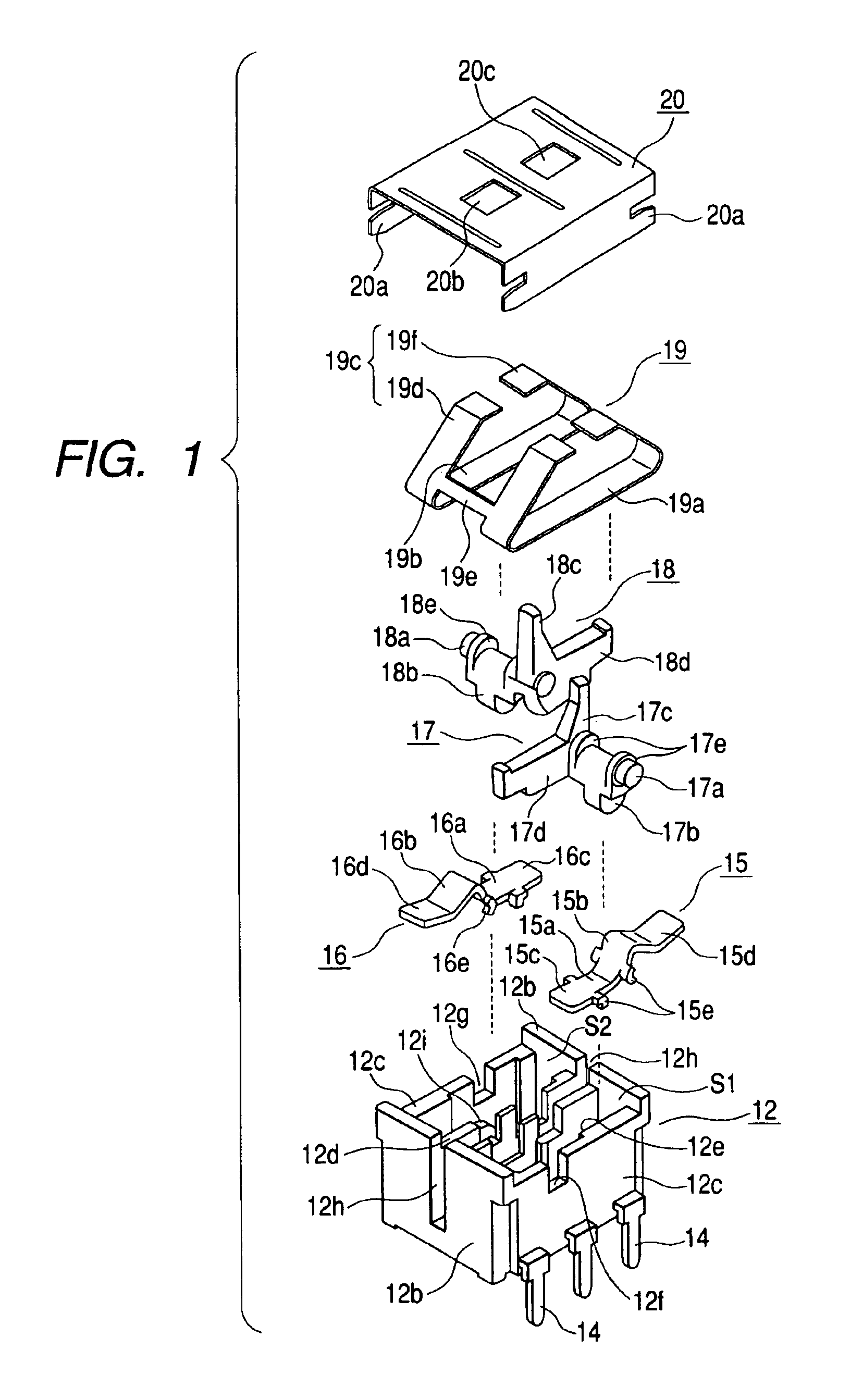
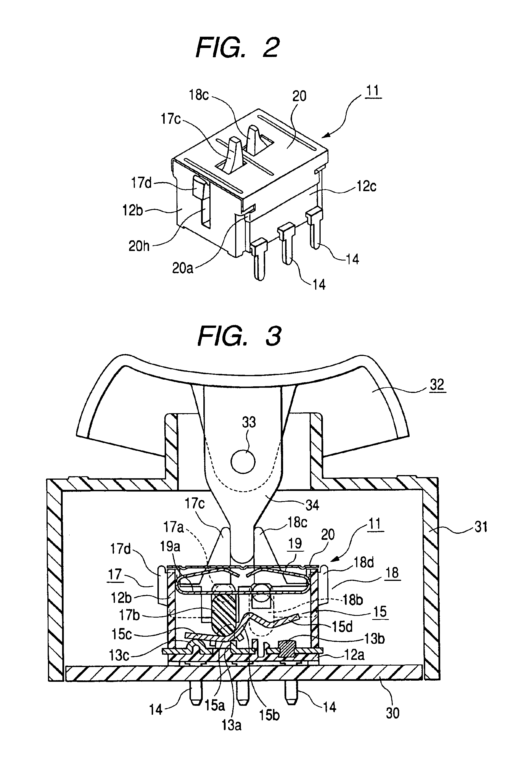
[0027]Preferred embodiments of the present invention will now be described with reference to the accompanying drawings. FIG. 1 is an exploded perspective view of a switch unit according to an embodiment of the present invention; FIG. 2 is a perspective view of the switch unit; FIG. 3 is a sectional view of a driving switch in its non-operating state, in which the switch unit is combined with a rocker-type operating knob; and FIG. 4 is a sectional view of the driving switch, as illustrated in FIG. 3, in its operating state.

[0028]Referring to these drawings, generally, a switch unit 11 comprises a case 12 in which sidewalls 12b and 12c and partition walls 12d are set up from a bottom wall 12a to form a pair of contact accommodation spaces S1 and S2; a fixed contact members 13a to 13c respectively disposed on the bottom wall 12a in the pair of contact accommodation spaces S1 and S2 by insert molding; a plurality of terminals 14 extending from the respective fixed contact members 13a to...


PUM


Abstract

A switch unit contains a case; a fixed contact members disposed on a bottom wall of the case; conductor plates rockably disposed on the bottom wall; driving bodies disposed on the conductor plates in a rotatable state in which the elevating movement thereof is allowed; a plate spring member for resiliently biasing the driving bodies; and a cover member for covering an upper opening of the case. The driving bodies are provided with pressed parts that protrude above the cover member. When the pressed part is driven to rotate laterally by the rocking operation of the operating knob, the driving body rotates, which causes the conductor plate to slide on the bottom wall. As a result, the switch unit is switched to its ON state.

Description

[0001]This application claims the benefit of priority to Japanese Patent Application No. 2003-359499 filed on Oct. 20, 2003, herein incorporated by reference.BACKGROUND OF THE INVENTION[0002]1. Field of the Invention[0003]The present invention relates to a switch device suitable for use in, for example, a driving switch of a vehicle-mounted power window apparatus, which is capable of selectively operating two sets of switch elements by rockably operating an operating knob.[0004]2. Description of the Related Art[0005]Conventionally, as a driving switch of a vehicle-mounted power switch, a driving switch is proposed in which two sets of slide-type switch elements are juxtaposed to each other and an operating rod of an operating knob is rockably operated to turn on the respective switch elements (for example, see Japanese Examined Patent Application Publication No. 5-80770).[0006]FIG. 11 is an explanatory view illustrating a conventional example of such a driving switch. In this drawin...

Claims


Application Information

Patent Timeline
Patent Type & Authority Patents(United States)
IPC IPC(8): H01H11/00H01H23/00H01H23/16H01H15/16H01H3/46H01H23/24H01H23/30
CPCH01H11/0018H01H23/168H01H23/003H01H23/24
Inventor SASAKI, MAKOTO
Owner ALPS ALPINE CO LTD
Why Eureka
Try Eureka