Check patentability & draft patents in minutes with Patsnap Eureka AI!

Multi-point subsurface measurement calibration

Inactive Publication Date: 2005-06-07
SCHLUMBERGER TECH CORP
View PDF16 Cites 3 Cited by
  • Summary
  • Abstract
  • Description
  • Claims
  • Application Information

AI Technical Summary

Benefits of technology

[0017]Still yet another aspect of the invention provides a method of calibrating a well-logging density sensor comprising emitting a first gamma ray signal into an aluminum alloy block disposed proximate to the sensor, measuring a first density sensor response from the first gamma ray signal, emitting a second gamma ray signal into a magnesium alloy block disposed proximate to the sensor, measuring a second density sensor response from the second gamma ray signal, emitting a third gamma ray signal into water disposed proximate to the sensor, measuring a third density sensor response from the third gamma ray signal, and determining a density sensor response function from the first density sensor response, the second density sensor response, and the third density response. In some embodiments, the method includes determining an expected range for a quality check response using water as a quality-check substance, emitting a quality check gamma ray signal into water disposed proximate to the sensor, measuring the quality check sensor response from the qual

Problems solved by technology

Further, the sensor efficiency at detecting gamma rays affects the count rate.

Method used


Image

  • Multi-point subsurface measurement calibration
  • Multi-point subsurface measurement calibration
  • Multi-point subsurface measurement calibration

Examples


Embodiment Construction

[0036]Techniques for calibrating subsurface measurement sensors are presented. A method according to the invention relates to a two-point calibration. Another method according to the invention relates to a quality-check for a calibration.

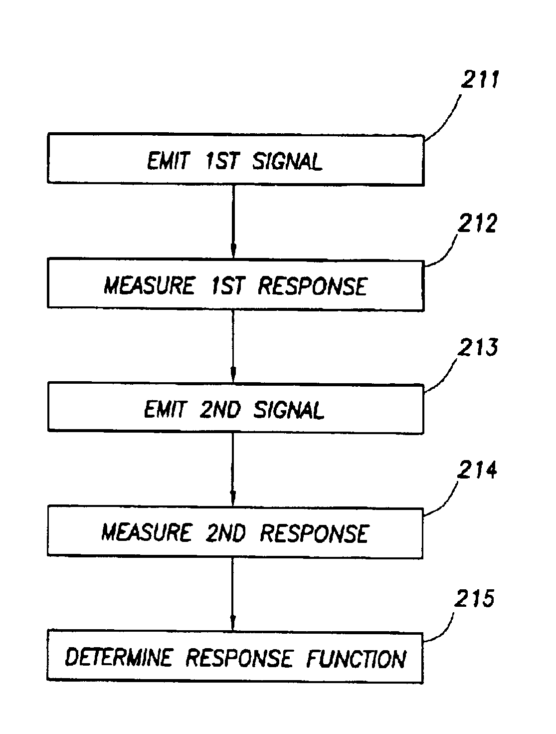
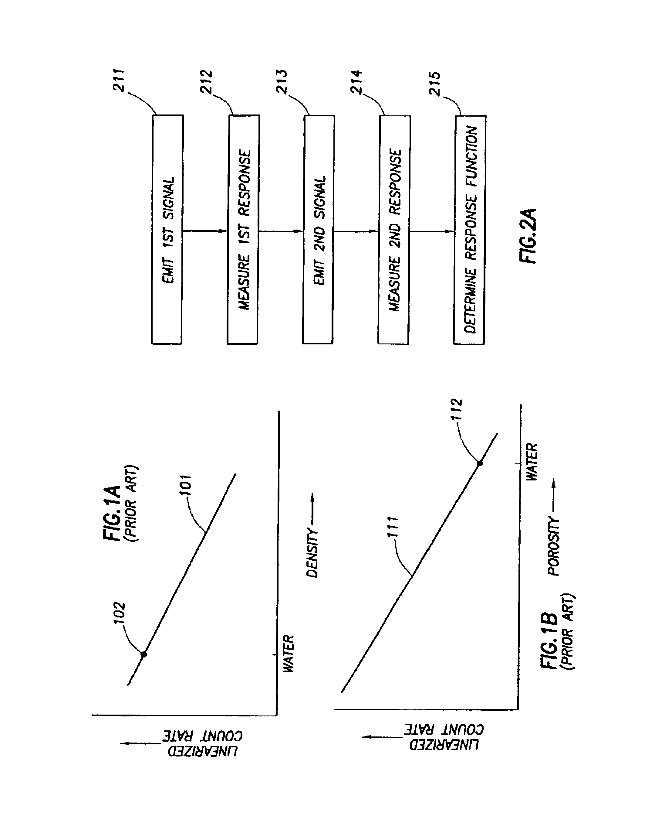
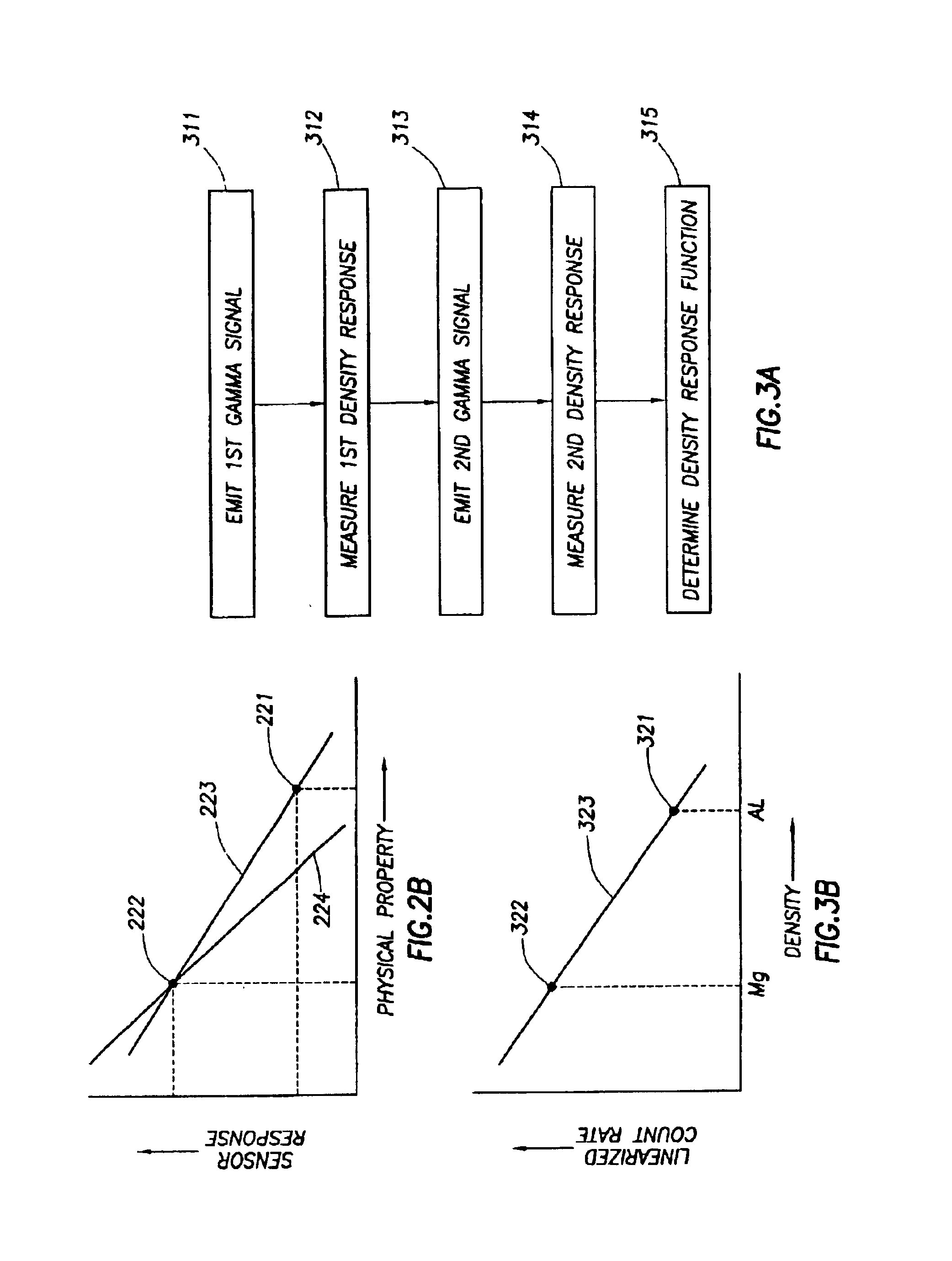
[0037]FIG. 2A shows one aspect of a method of calibrating a sensor according to the invention. The method according to this embodiment includes emitting a first signal into a first calibration substance 211 and measuring a first sensor response from the first signal 212. A sensor response is the count rate measurement made by the sensor with a particular substance having a known property disposed proximate to the sensor. A sensor response determines a raw count rate that correlates to a known physical property. The method next includes emitting a second signal into a second calibration substance 213 and measuring a second sensor response with the second calibration substance 214. The method then includes determining a response function based on the ...


PUM


Abstract

Techniques for calibrating well-logging sensors comprising emitting a first signal into a first calibration substance disposed proximate to the sensor, measuring a first sensor response from the first signal, emitting a second signal into a second calibration substance disposed proximate to the sensor, measuring a second sensor response from the second signal, and determining a sensor response function from the first sensor response and the second sensor response. One embodiment includes providing a well-logging sensor having a known response function, determining an expected range of a quality check response of the sensor using a quality-check substance with known properties, emitting a quality check signal into the quality-check substance, measuring the quality check response from the quality check signal, and comparing the expected range with the quality check response.

Description

CROSS REFERENCE TO RELATED APPLICATIONS[0001]This application claims the benefit of U.S. Provisional Patent Application 60 / 345,615, filed on Oct. 19, 2001.BACKGROUND OF INVENTION[0002]The invention relates generally to calibration of sensors. More specifically, the invention relates to an improved method for calibrating sensors adapted for measurement of subsurface properties.[0003]In the oil-drilling and exploration industry, many types of sensors are used to evaluate subsurface formations traversed by a borehole, commonly referred to as well logging. Sensors measure a phenomenon that is related to a physical property of the formation, such as the density or the porosity. A particular formation property can be determined by measuring a phenomenon related to the formation property and calculating the formation property based on the relationship between the measured phenomenon and the desired formation property. In order to obtain useful information about the formation property, it i...

Claims


Application Information

Patent Timeline
IPC IPC(8): G01V13/00
CPCG01V13/00
Inventor EVANS, MICHAEL L.ORTENZI, LUCARADTKE, RICHARD J.
Owner SCHLUMBERGER TECH CORP
Features
  • R&D
  • Intellectual Property
  • Life Sciences
  • Materials
  • Tech Scout
  • Unparalleled Data Quality
  • Higher Quality Content
  • 60% Fewer Hallucinations
Learn More