
Progressive CPU sleep state duty cycle to limit peak power of multiple computers on shared power distribution unit

a technology of power distribution unit and sleep state, which is applied in the direction of power supply for data processing, liquid/fluent solid measurement, instruments, etc., can solve the problems of system inefficiency and high cost, and the power management of the servers on the rack is performed in a somewhat inefficient and expensive manner

Inactive Publication Date: 2005-06-07
SAMSUNG ELECTRONICS CO LTD
View PDF13 Cites 151 Cited by
  • Summary
  • Abstract
  • Description
  • Claims
  • Application Information

AI Technical Summary

Benefits of technology

[0010]Briefly, a power management system for distributing power to a plurality of computers is employed. In one embodiment, the power management system monitors the power consumption of the various computers and regulates the overall power demand by momentarily putting microproce...

Problems solved by technology

Generally, power management of the servers on the rack is performed in a somewhat inefficient and expensive manner.
Therefore, while the above described system may be reliable, such a system is inefficient and expensive for certain applications.

Method used


Image

  • Progressive CPU sleep state duty cycle to limit peak power of multiple computers on shared power distribution unit
  • Progressive CPU sleep state duty cycle to limit peak power of multiple computers on shared power distribution unit
  • Progressive CPU sleep state duty cycle to limit peak power of multiple computers on shared power distribution unit

Examples


Embodiment Construction

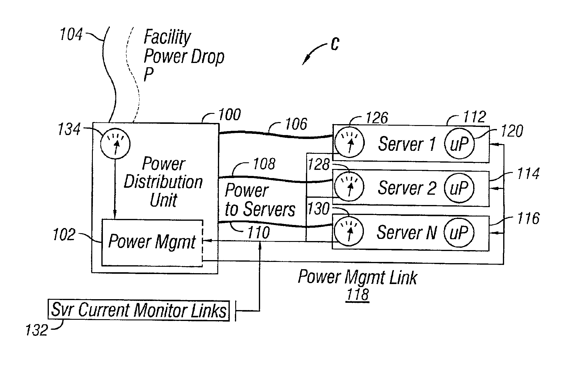
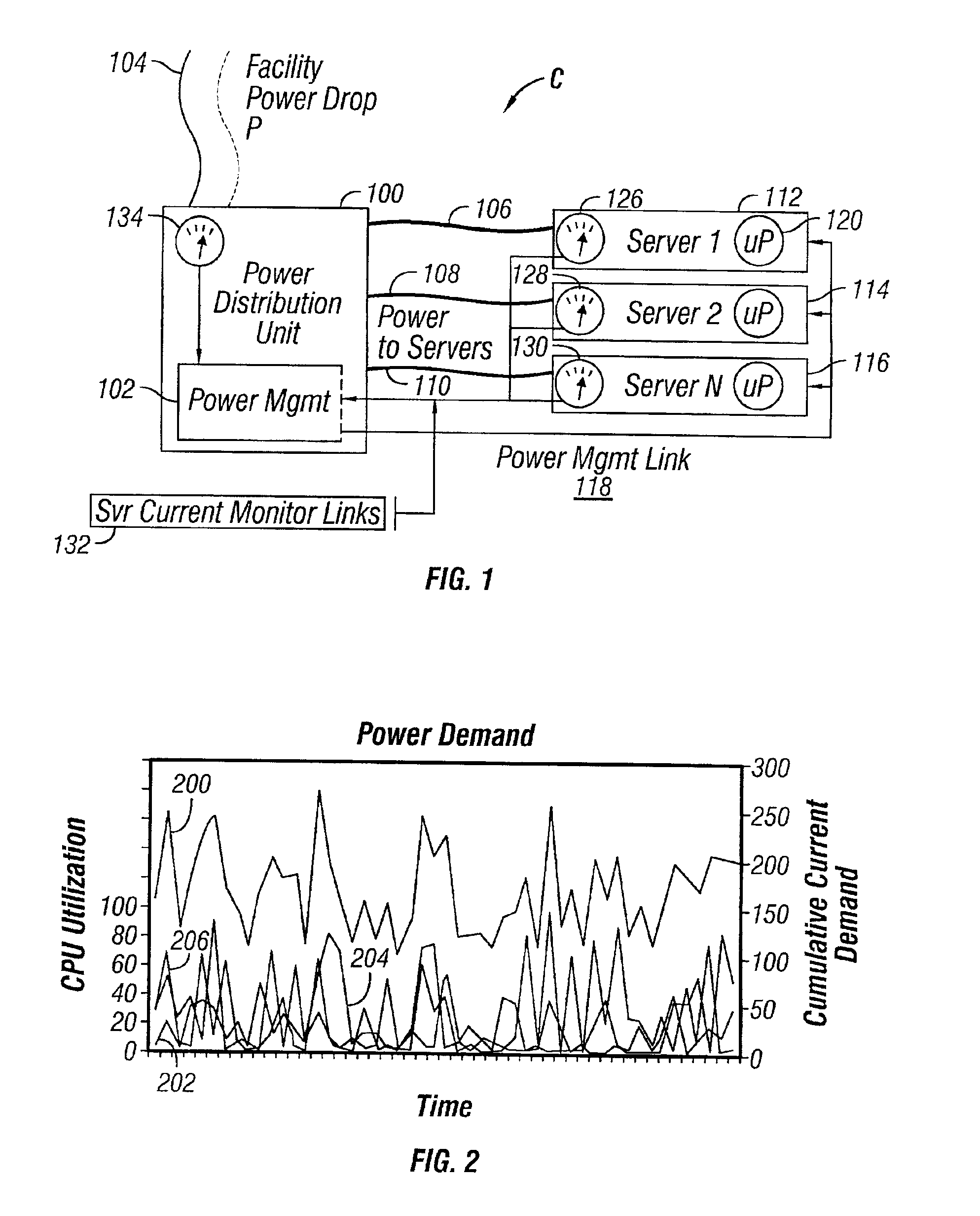
[0019]FIG. 1 is a block diagram of an embodiment of a computer system C in accordance with the present invention. The computer system C typically includes various computing devices, such as servers 112, 114 and 116. For illustrative purposes, three (3) servers are shown in FIG. 1. However, one skilled in the art would recognize that there could be more than three (3) servers in a system powered by a common power source. Each server generally includes a microprocessor and a current monitoring device. For example, the server 112 includes a microprocessor 120 and a current monitoring device 126. The microprocessor 120 can be any type of general central processing unit (CPU), such as an Intel Pentium-type microprocessor. The servers 112, 114 and 116 are powered by a power distribution unit 100. Power P from a facility power drop is provided to the power distribution unit 100 via power lines 104.

[0020]In this embodiment, the power distribution unit 100 includes a power management control...


PUM


Abstract

A method and apparatus for distributing power to a plurality of computers in a network. A power management system including a feed-back mechanism, is employed to monitor power consumptions of the plurality of computers. Should the overall power consumption reach a threshold, the power management system instructs the microprocessors in the plurality of computers to enter into a lower power state, such as a sleep state, for a certain duration, thus lowering overall power.

Description

CROSS-REFERENCE TO RELATED APPLICATIONS[0001]None.STATEMENTS REGARDING FEDERALLY SPONSORED RESEARCH OR DEVELOPMENT[0002]Not applicable.REFERENCE TO A MICROFICHE APPENDIX[0003]Not applicable.BACKGROUND OF THE INVENTION[0004]1. Field of the Invention[0005]The present invention relates to power management of a computer system and, more particularly, utilizing a power distribution unit to control the amount of power consumed by a network of computers.[0006]2. Description of the Related Art[0007]As computers get smaller, the computer's power density per unit of volume increases. That is, while the computer's size may decrease, the power demand of the computer generally remains the same. In some applications, a plurality of computer servers in a network are mounted onto a rack. The servers and other electronic components on the rack are fed by a common power source.[0008]Generally, power management of the servers on the rack is performed in a somewhat inefficient and expensive manner. In ...

Claims


Application Information

Patent Timeline
IPC IPC(8): G06F1/32
CPCG06F1/3203
Inventor KOENEN, DAVID J.
Owner SAMSUNG ELECTRONICS CO LTD
Learn More