Joint assembly of vacuum cleaner and vacuum cleaner having the same

a technology of vacuum cleaner and joint, which is applied in the field of vacuum cleaner, can solve the problems of increasing user's fatigue, increasing user's fatigue, and fatigue after using the vacuum cleaner, and achieve the effect of preventing user fatigu

Inactive Publication Date: 2005-06-14
SAMSUNG GWANGJU ELECTRONICS CO LTD
View PDF19 Cites 32 Cited by
  • Summary
  • Abstract
  • Description
  • Claims
  • Application Information

AI Technical Summary

Benefits of technology

[0009]The present invention has been made to overcome the above-mentioned problems of the prior art. Accordingly, it is an object of the present invention ...

Problems solved by technology

When the user performs this cleaning operation for a long period of time, the user may feel tired and hurt his/her back.
In addition, when the vacuum cleaner 100 is used while gripping the handle 140 with only one hand, the load of the suc...

Method used


Image

  • Joint assembly of vacuum cleaner and vacuum cleaner having the same
  • Joint assembly of vacuum cleaner and vacuum cleaner having the same
  • Joint assembly of vacuum cleaner and vacuum cleaner having the same

Examples


Embodiment Construction

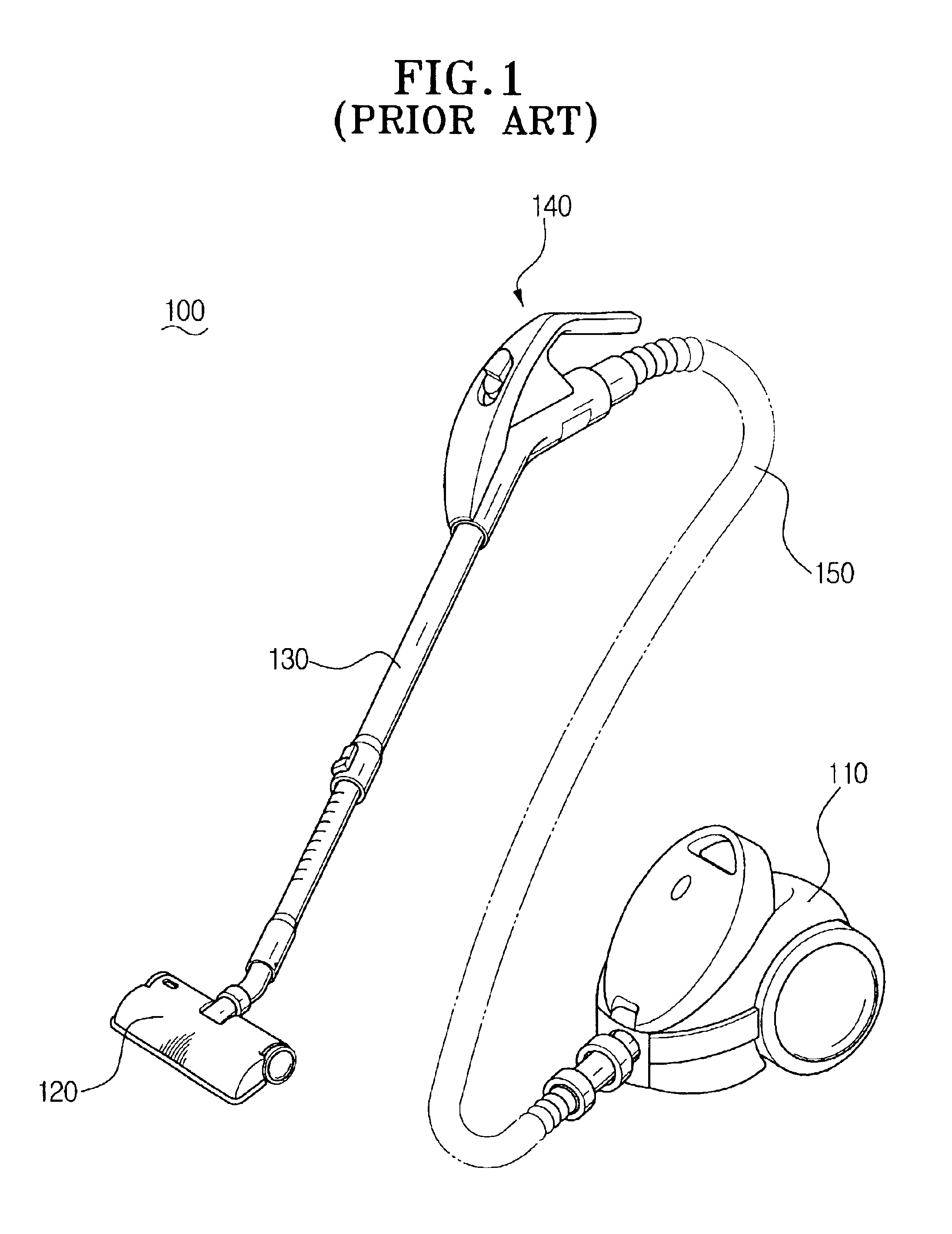
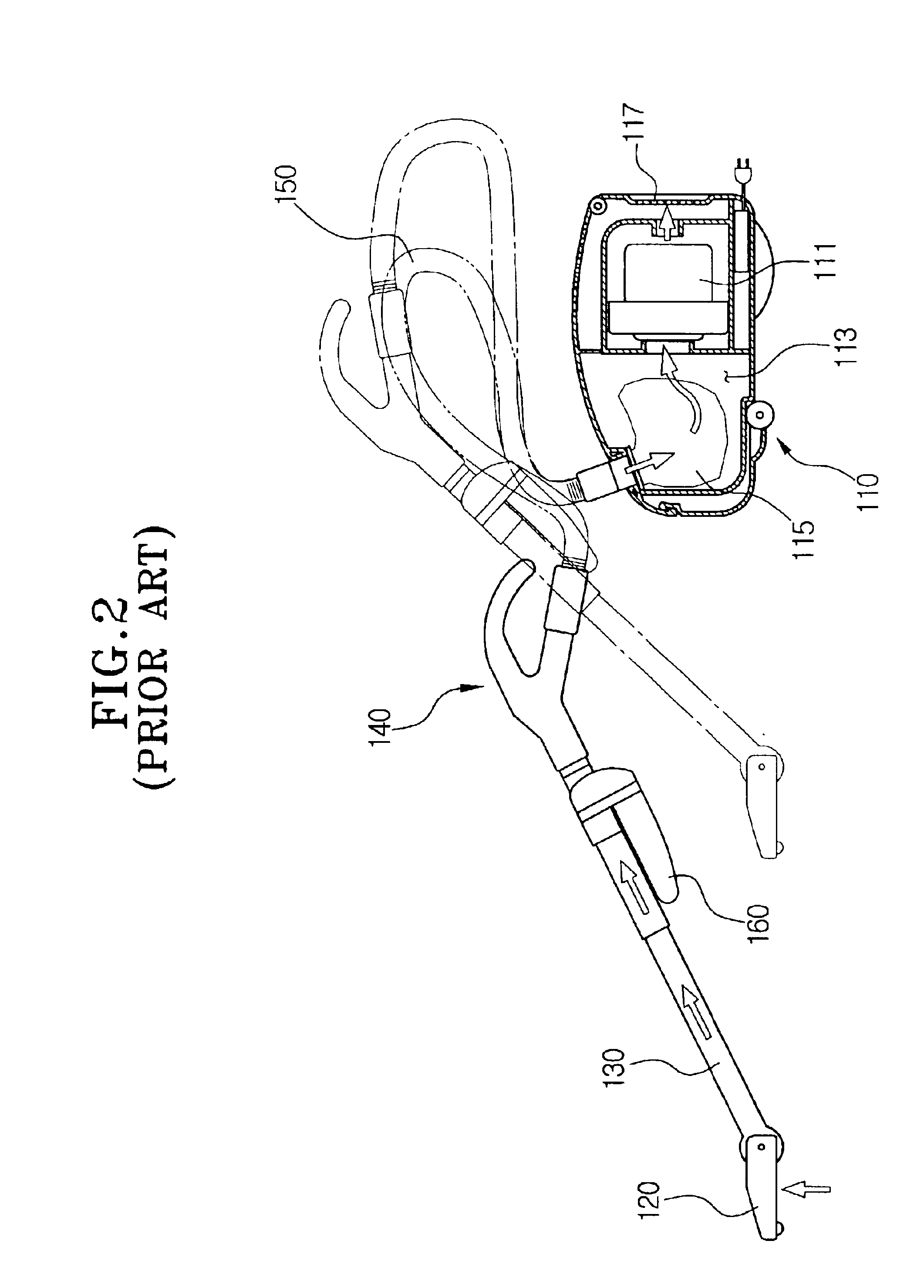
[0028]Hereinbelow, the preferred embodiments of the present invention will be described in greater detail by referring to the appended drawings. For the description of the preferred embodiments of the present invention, elements having the same function and structure with the elements of the conventional vacuum cleaner described and shown in FIGS. 1 and 2, will be given the same reference numerals and the description of the same elements will be omitted.

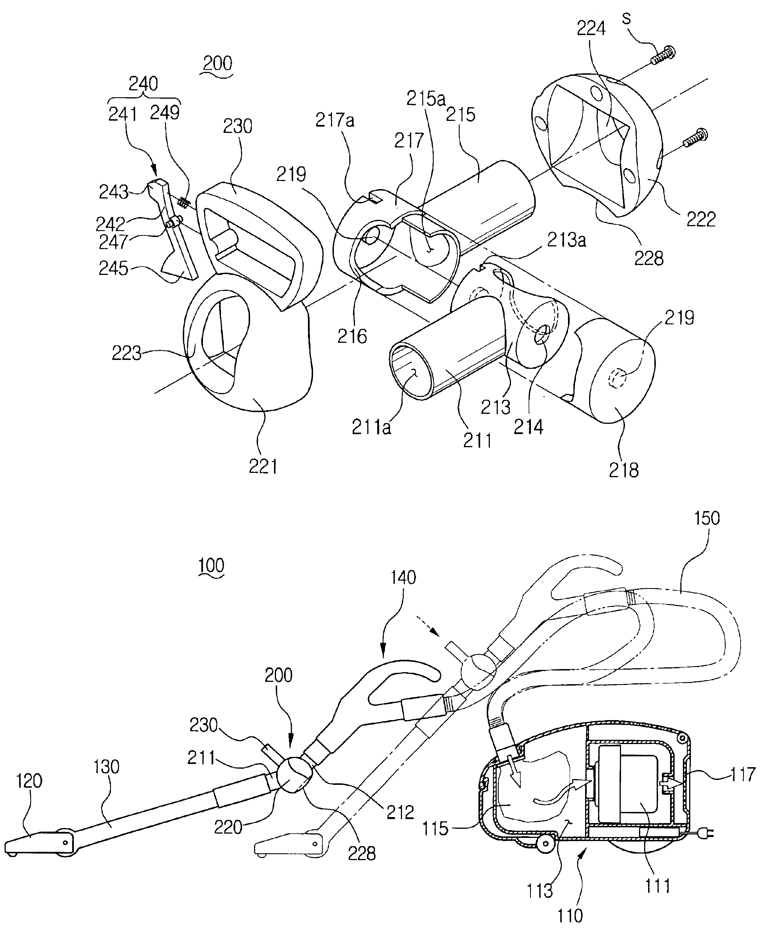
[0029]Referring to FIG. 3, a vacuum cleaner 100 according to the present invention has a joint assembly 200 removably installed between an extension pipe 130 and a handle 140. The joint assembly 200 includes a joint body 210 whose ends are respectively connected with the extension pipe 130 and the handle 140, and a supplementary handle 230 protruding from an outer surface of the joint assembly 200. The extension pipe 130 is connected to be rotated within a predetermined range with respect to the handle 140 by the joint assembly 200.

[...


PUM


Abstract

A vacuum cleaner having a joint assembly to selectively rotate an extension pipe with respect to a handle. The joint assembly has a joint body removably installed between the extension pipe and the handle to allow the extension pipe 130 to rotate with respect to the handle 140 within a predetermined range. Also included on the joint assembly is a supplemental handle protruding from an outer surface of the joint body. The joint assembly and supplemental handle allow the user to clean under a bed or a desk without having to bend his/her back too much. Therefore, the user is not easily fatigued even when he/she cleans under the desk or bed.

Description

FIELD OF INVENTION[0001]The present invention relates to a vacuum cleaner, and more particularly, to a joint assembly disposed between an extension pipe and a handle in order to help a user feel less fatigued when using a vacuum cleaner.BACKGROUND OF THE INVENTION[0002]As shown in FIGS. 1 and 2, a conventional vacuum cleaner 100 includes a vacuum cleaner body 110 having a suction motor 111, a dust-collecting chamber 113, a suction assembly 120 to draw in dust and air on a cleaning surface, an extension pipe 130 installed between the suction assembly 120 and the vacuum cleaner body 110 in order to form an air passage, a handle 140, and an extension hose 150.[0003]The air drawn through the suction assembly 120 flows to the dust-collecting chamber 113 of the vacuum cleaner body 110 after passing through the extension pipe 130, the handle 140, and the extension hose 150 as shown by the arrow in FIG. 2. Filth contained in the air drawn into the dust-collecting chamber 113 is filtered by ...

Claims


Application Information

Patent Timeline
IPC IPC(8): A47L9/16A47L9/10A47L9/32A47L9/24
CPCA47L9/327A47L9/242A47L9/16F16L27/0837A47L9/24
Inventor JIN, HYOUNG-JONGOH, JANG-KEUN
Owner SAMSUNG GWANGJU ELECTRONICS CO LTD
Why Eureka
Try Eureka