
Slide rail adjustment for grader blade

a technology of grader blades and slide rails, which is applied in the direction of mechanical machines/dredgers, soil shifting machines/dredgers, constructions, etc., can solve the problems of high load on the system, material contamination, and inconvenient adjustment of the slide rails, so as to reduce the tolerance

Inactive Publication Date: 2005-06-14
VOLVO MOTOR GRADERS
View PDF12 Cites 9 Cited by
  • Summary
  • Abstract
  • Description
  • Claims
  • Application Information

AI Technical Summary

Benefits of technology

"The invention is a motor grader blade support arrangement that includes a blade support structure with upper and lower bearing arrangements that engage the blade's slide rails for longitudinal sliding movement. The bearing arrangements have an adjustment mechanism to compensate for bearing wear and grease fittings for easy adjustment. The arrangement also includes two hydraulic cylinders that act as intermediaries between the bearing holder and the slide bearing. The bearing holder has a U-shaped channel for receiving the removable bearing. The invention provides improved stability and durability of the motor grader blade support arrangement."

Problems solved by technology

The grading blade of a motor grader is subject to a host of adjustments and the nature of the mechanism and the nature of the application subjects the system to high loads.
In addition, the operating conditions of the motor grader often cause material contamination and which is a particular problem for the slide mechanism of a grader blade as accelerated wear can occur.
Typically these systems use a number of large bolts and shims, however, the adjustment thereof is not convenient and requires specialized personnel and tools which are not normally available to the operator.

Method used


Image

  • Slide rail adjustment for grader blade
  • Slide rail adjustment for grader blade
  • Slide rail adjustment for grader blade

Examples


Embodiment Construction

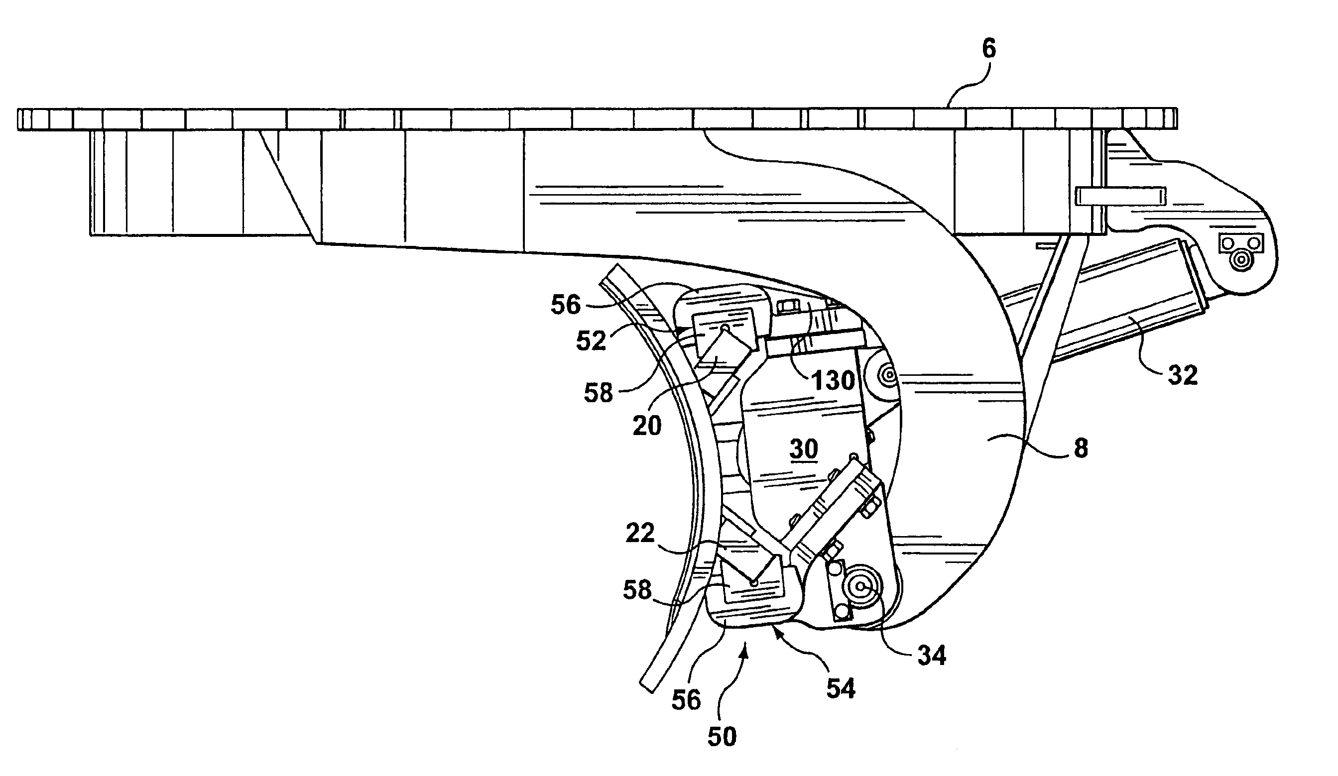
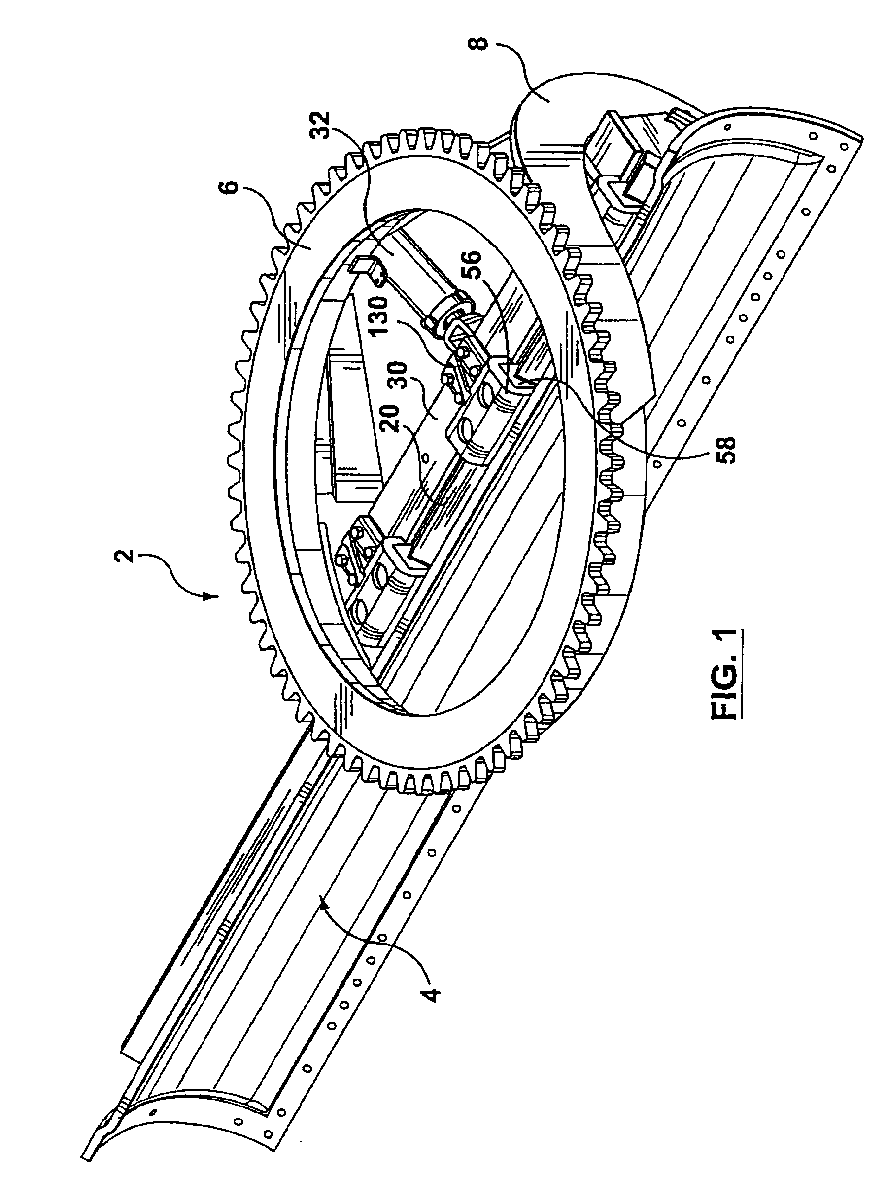
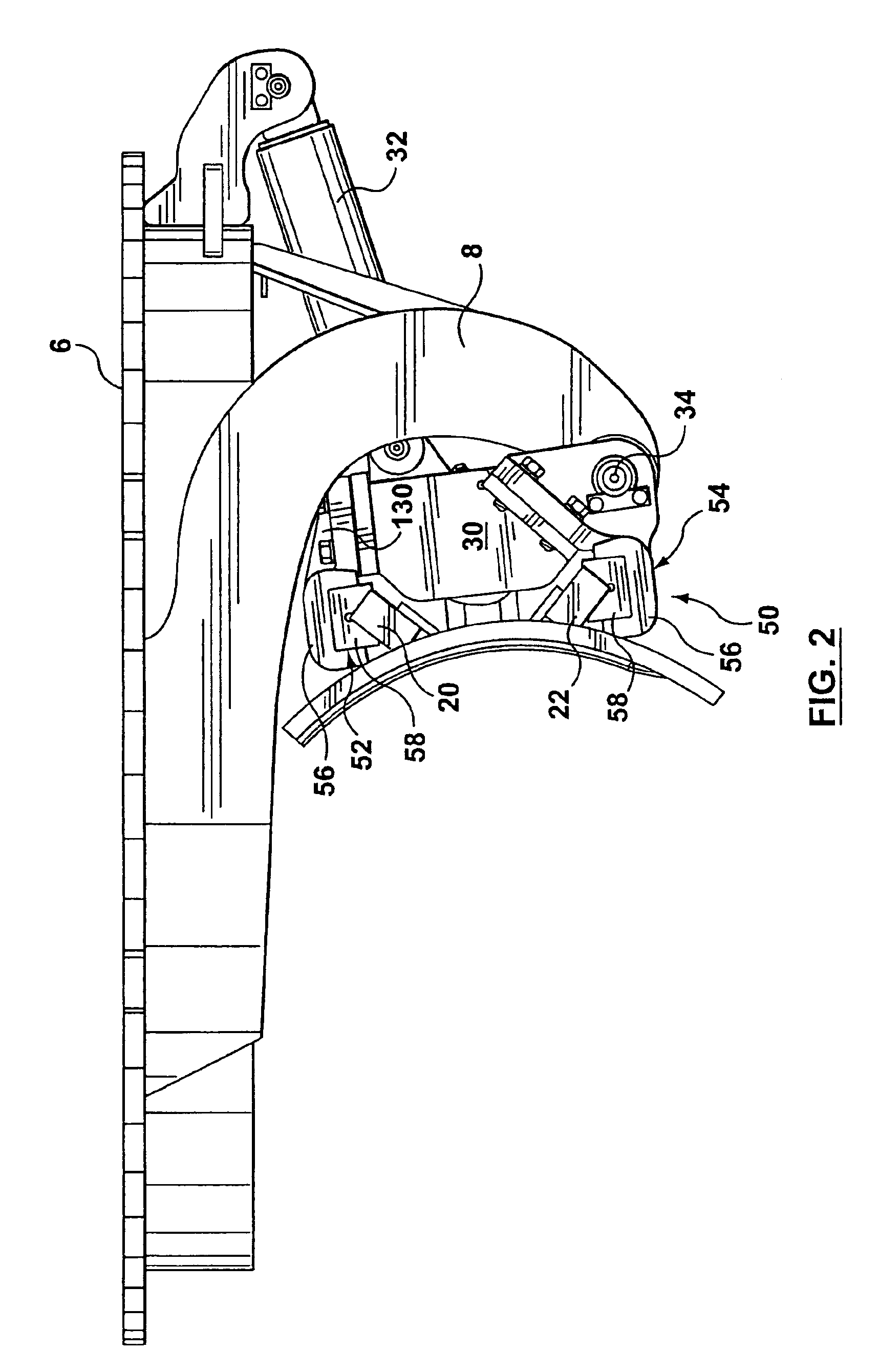
[0021]The blade support arrangement 2 for a motor grader is shown in FIG. 1 with the slidable blade 4 offset relative to the rotatable ring gear 6. The support arrangement includes downwardly extending arms 8 which pivotally support the center pivotting structure 30 at a lower edge thereof. This support structure 30 includes associated upper bearing arrangements 52 and lower bearing arrangements 54 attached thereto.

[0022]The grader blade 4 has an upper slide rail 20 fixed to a back surface of the blade and a lower slide rail 22 fixed to the back surface. The upper bearing arrangements 52 and lower bearing arrangements 54 serve to secure the blade 4 to the support structure 30 and allow sliding movement of the blade as the slide rails slide within the bearing arrangements. The hydraulic cylinder 32 allows tilting of the support structure 30 which in turn causes tilting of the blade 4.

[0023]Details of the lower bearing arrangement 54 are shown in the exploded view of FIG. 3. A bearing...


PUM


Abstract

A bearing support arrangement for a grader blade uses short stroke hydraulic cylinders to compensate for wear between slide bearings and slide rails of the grader blade. The cylinders are preferably pressurized by grease and a grease fitting is provided for each cylinder to provide convenient access, to allow service by the operator. Preferably the cylinders are located in a generally closed cavity between the bearing support holder and the slide bearing.

Description

[0001]This application is a divisional application of U.S. patent application Ser. No. 10 / 073,110, filed Feb. 12, 2002 now U.S. Pat. No. 6,799,640.FIELD OF THE INVENTION[0002]The present invention relates to motor graders and in particular, relates to a bearing slide arrangement for a motor grader blade.BACKGROUND OF THE INVENTION[0003]The grading blade of a motor grader is subject to a host of adjustments and the nature of the mechanism and the nature of the application subjects the system to high loads. In addition, the operating conditions of the motor grader often cause material contamination and which is a particular problem for the slide mechanism of a grader blade as accelerated wear can occur.[0004]Motor grader blades all typically include a slide adjustment for varying the position of the blade beneath the motor grader. Slide rails are provided on the rear surface of the grader blade and slide bearings are provided which engage the rails and allow the rail to slide therebet...

Claims


Application Information

Patent Timeline
Patent Type & Authority Patents(United States)
IPC IPC(8): E02F3/76E02F3/815
CPCE02F3/8157
Inventor MCGUGAN, EDWARD
Owner VOLVO MOTOR GRADERS
Learn More