Keyboard support bracket structure

a technology for supporting brackets and keyboards, applied in the direction of machine supports, building scaffolds, variable height tables, etc., can solve the problems of limited space between the bottom and the floor, insufficient leg room to accommodate user leg movements, and increased space, so as to reduce the wear of related elements, reduce the fixed point connection relationship, and increase the service life of products

Inactive Publication Date: 2005-06-14
PUU RONG INDS
View PDF22 Cites 29 Cited by
  • Summary
  • Abstract
  • Description
  • Claims
  • Application Information

AI Technical Summary

Benefits of technology

[0008]Therefore the primary object of the invention is to resolve the aforesaid disadvantages and overcome the drawbacks of the prior art. The invention does not adopt conventional fixed pivotal connection for four points axles. Instead, one of the axles is connected movably. The fixed point connection relationship for friction is eliminated. Then other three fixed points axles may be moved endlessly. Thereby wearing of the related elements may be reduced and service life of the product may increase. Noise caused by movements can also be prevented. As there is no restriction of the friction force, the linkage mechanism of the invention enables user's hand to apply force easily. The keyboard support bracket also is more suitable for people to use. In addition, when the angle of the side arm of the invention increases when it is changed from closing to the highest position of the desktop to the lowest position, the included angle of the holding bracket relative to the desktop must decrease, namely, the support bracket inclines to a selected angle to suit user's forearm when the side arm is moved downwards. Therefore, user's forearm may have an effective support whatever operating positions user's forearm is taking. Thus it can better conform to ergonomics and reduce the risk of injury.
[0009]In order to achieve the foregoing object, the invention includes a mounting bracket fastening to a desktop, an upper arm pivotally engaged with the mounting bracket through a first axle, a side arm pivotally coupled on two sides of mounting bracket through a second axle, and a holding bracket pivotally engaged with the upper arm through a third axle and pivotally engaged with the side arm through a fourth axle. The fourth axle is movably connected to release the constrained position of the holding bracket, then the first, second and third axles may be moved to perform vertical adjustment endlessly. The keyboard support structure thus made uses a fewer number of elements and may be moved with less effort.

Problems solved by technology

Because the parallelogram linkage is fastened to the lower side of the keyboard support bracket, the space between the bottom and the floor is limited.
Leg room is not adequate to accommodate leg movements of users.
While it addresses the shortcomings of the aforesaid patent and uses a non-parallelogram linkage to increase the leg room, its linkage mechanism is still fastened to the lower side of the keyboard support bracket, and the increased space is limited.
However it still has problems remained to be overcome, notably:
As the side arm and the stopping means are made of metal, in terms of applying forces easily and providing frictional forces required for latching, they cannot generate a desirable coordination during the movement.
The metal also generates heat and noise under friction.
The arched end tends to wear off after used for a long period of time.
As a result, it could cause injury to users when operating in such a posture for a long period of time.

Method used


Image

  • Keyboard support bracket structure
  • Keyboard support bracket structure
  • Keyboard support bracket structure

Examples


Embodiment Construction

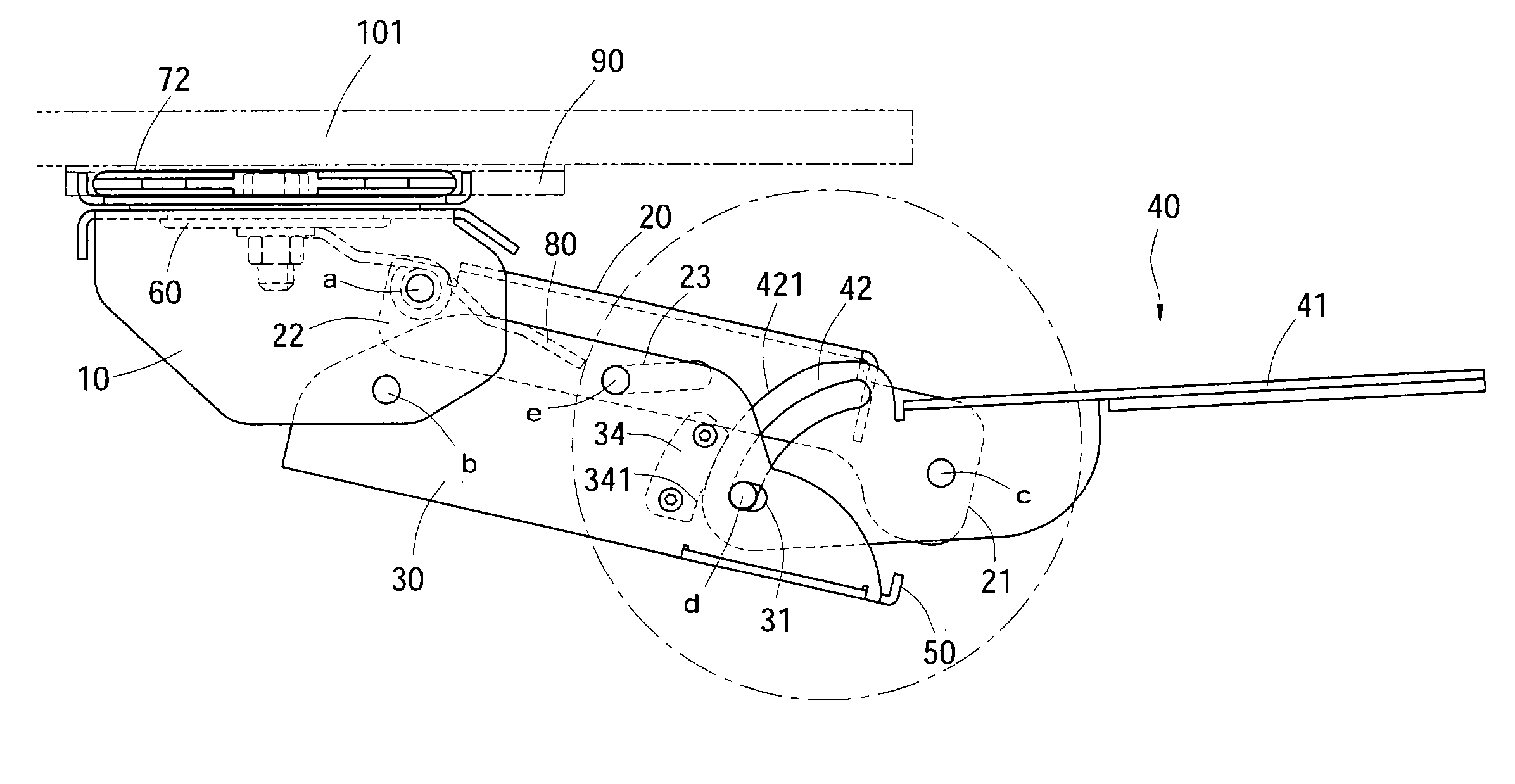
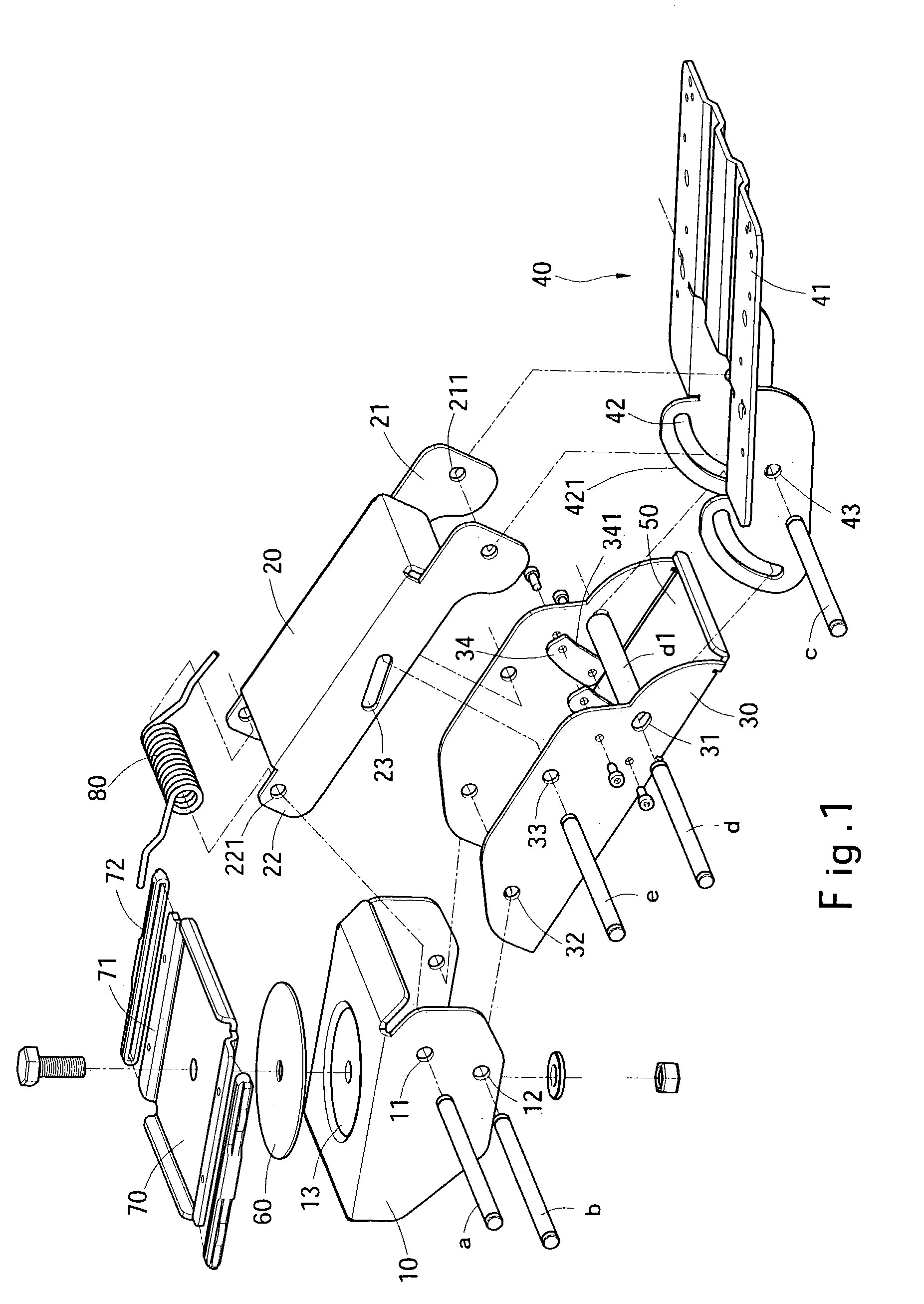
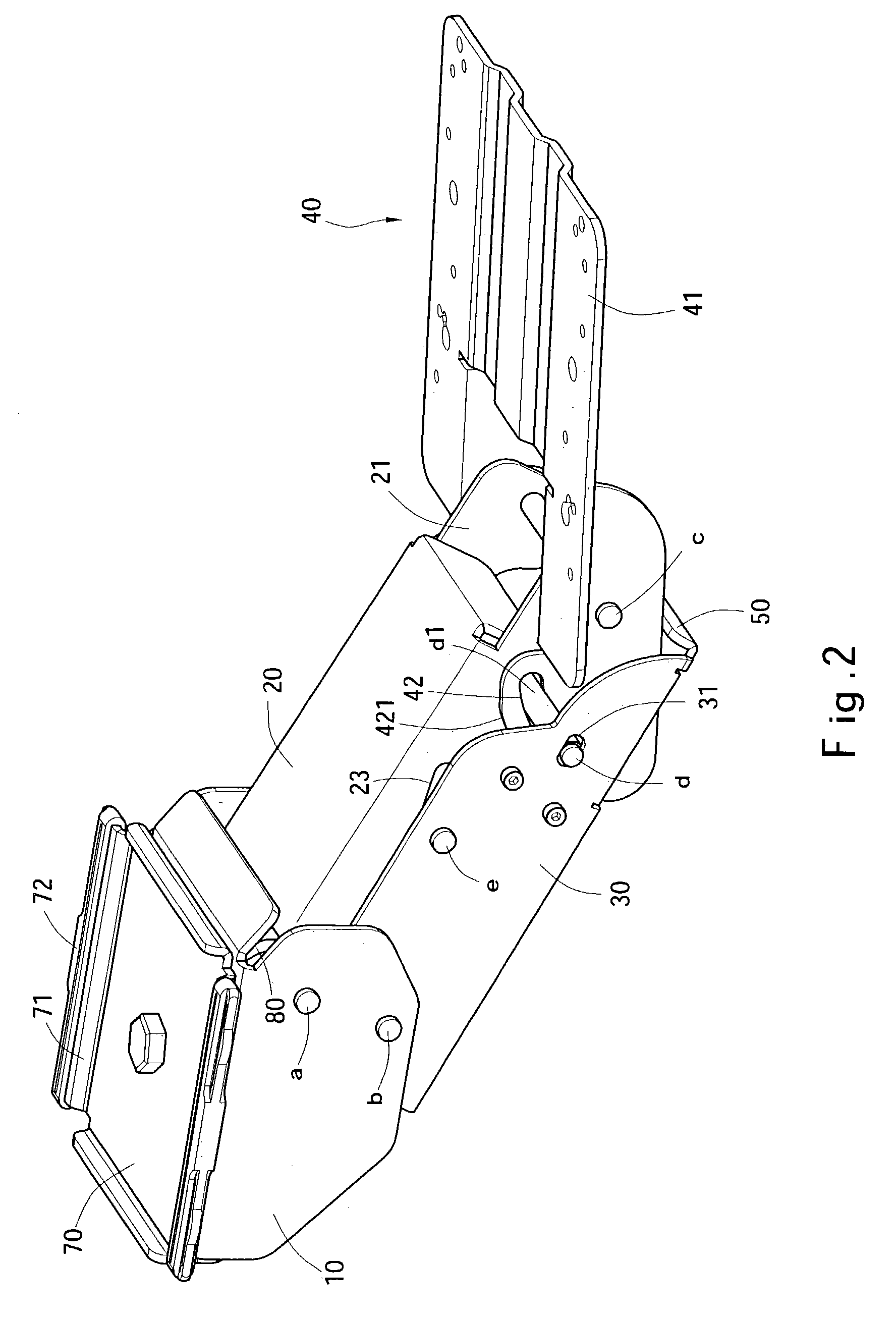
[0017]Please referring to FIGS. 1, 2, 3A and 5, the present invention is located under a desktop 101 and may be moved horizontally and vertically relative to the desktop 101 to a desired location for holding a keyboard (not shown in the drawings) at an operating position. The invention includes a mounting bracket 10 fastening to the desktop 101, an upper arm 20 pivotally engaged with the mounting bracket 10 through a first axle a which runs through pivot holes 11 and 221, a side arm 30 pivotally coupled on two sides of the mounting bracket 10 through a second axle b which runs through pivot holes 12 and 32, and a holding bracket 40 pivotally engaged with the upper arm 20 through a third axle c and pivotally engaged with the side arm 30 through a fourth axle d that run through pivot holes 211 and 43. The first axle a is coupled with an elastic restoring element 80 which provides a biased pressure upwards.

[0018]The pivot holes 221 and 211 of the upper arm 20 are formed respectively on...


PUM


Abstract

An angularly adjustable keyboard support bracket includes a mounting rack attached to a desktop, a movable arm coupled with the mounting rack through a pin, and a bracing rack coupled with another end of the movable arm through another pin for holding a tray. A rotary mechanism is located between the bracing rack and the tray to enable the tray to swivel to the left side and the right side for a selected angle relative to the bracing rack to provide users with a desired operating angle.

Description

FIELD OF THE INVENTION[0001]The present invention relates to a keyboard support bracket structure and particularly to a keyboard support bracket for holding a keyboard and that is movable horizontally and vertically to suit user's operating position.BACKGROUND OF THE INVENTION[0002]Computer has been widely used by individuals and companies nowadays. When the computer is in use, in order to avoid the keyboard from occupying too much desktop space and take into account of ergonomics to prevent users from hand injury caused by taking the same posture for a long period of time during operation, a keyboard support bracket has been developed to suit user's posture and hand position, and to make adjustment endlessly.[0003]There are plenty of keyboard support brackets proposed in the prior art. For instance, U.S. Pat. No. 4,616,798 discloses an adjustable support for CRT keyboard. It has a bracket holding a keyboard and connecting to a parallelogram linkage located underside a desk. Because...

Claims


Application Information

Patent Timeline
Patent Type & Authority Patents(United States)
IPC IPC(8): A47B21/03A47B21/00F16M11/08F16M11/04F16M11/02
CPCA47B21/0314F16M11/04F16M11/041F16M13/02F16M11/10F16M11/2064F16M11/2092F16M11/08
Inventor LIN, SHENG-HSIUNG
Owner PUU RONG INDS
Why Eureka
Try Eureka