Methods and apparatus for assembling gas turbine engines

a gas turbine engine and assembly method technology, applied in the direction of machines/engines, forging/pressing/hammering apparatus, liquid fuel engines, etc., can solve the problems of increased non-uniform flow field pressure, adversely affecting engine operation, and expanding the affected area further upstream

Inactive Publication Date: 2005-06-14
GENERAL ELECTRIC CO
View PDF16 Cites 71 Cited by
  • Summary
  • Abstract
  • Description
  • Claims
  • Application Information

AI Technical Summary

Problems solved by technology

During operation, blockage created by the struts may induce a non-uniform flow field upstream of the strut and produce a local high pressure area in the vicinity of each strut leading edge which may adversely affect engine operations.
Furthermore, within at least some known gas turbine engines, when variable bleed valve (VBV) doors are opened, the non-uniformity of the flow field pressure increases and the affected area expands further upstream.

Method used


Image

  • Methods and apparatus for assembling gas turbine engines
  • Methods and apparatus for assembling gas turbine engines
  • Methods and apparatus for assembling gas turbine engines

Examples


Embodiment Construction

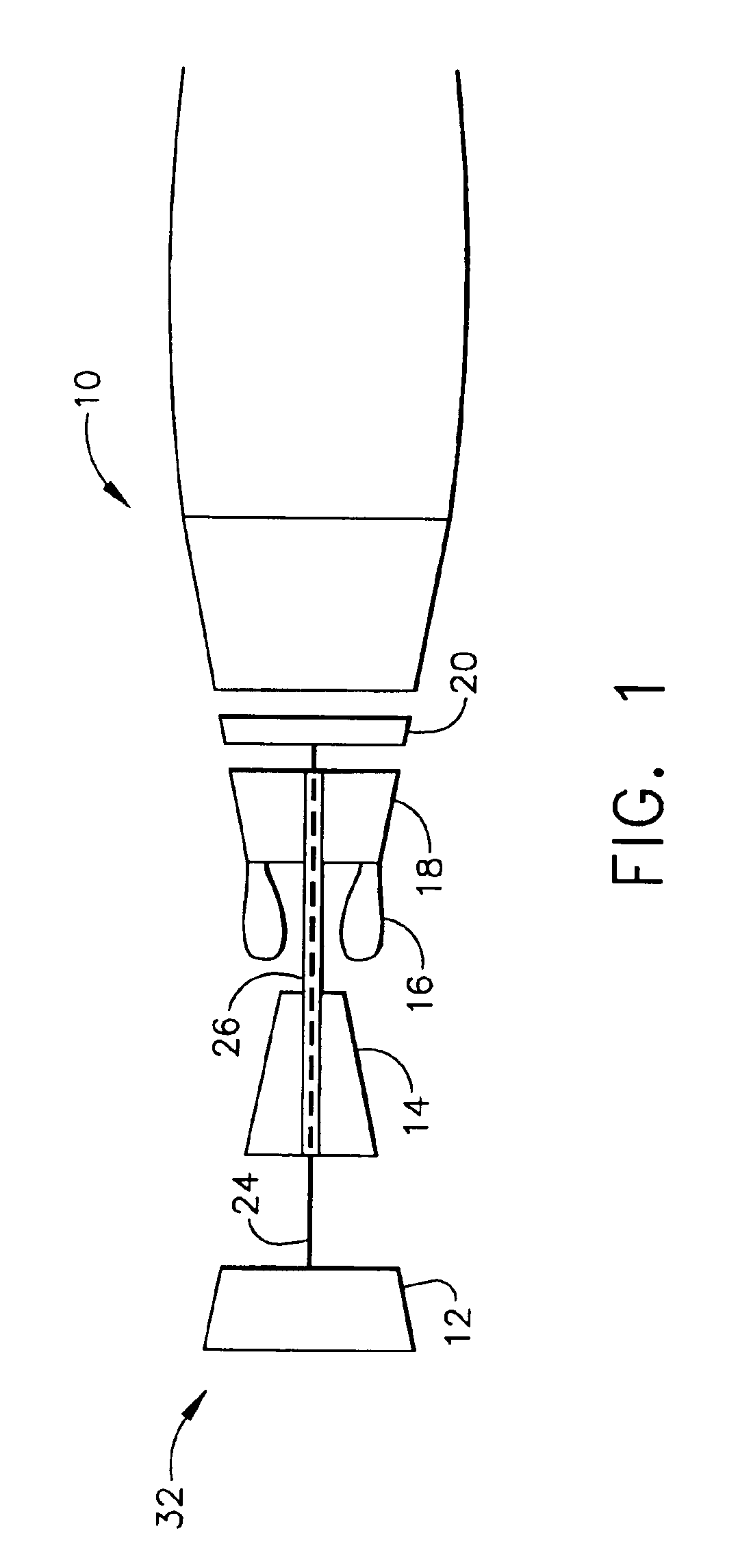
[0017]FIG. 1 is a schematic illustration of a gas turbine engine 10 including a low pressure compressor 12, a high pressure compressor 14, and a combustor assembly 16. Engine 10 also includes a high pressure turbine 18, and a low pressure turbine 20 arranged in a serial, axial flow relationship. Compressor 12 and turbine 20 are coupled by a first shaft 24, and compressor 14 and turbine 18 are coupled by a second shaft 26. In one embodiment, engine 10 is an GE90 engine commercially available from General Electric Company, Cincinnati, Ohio.

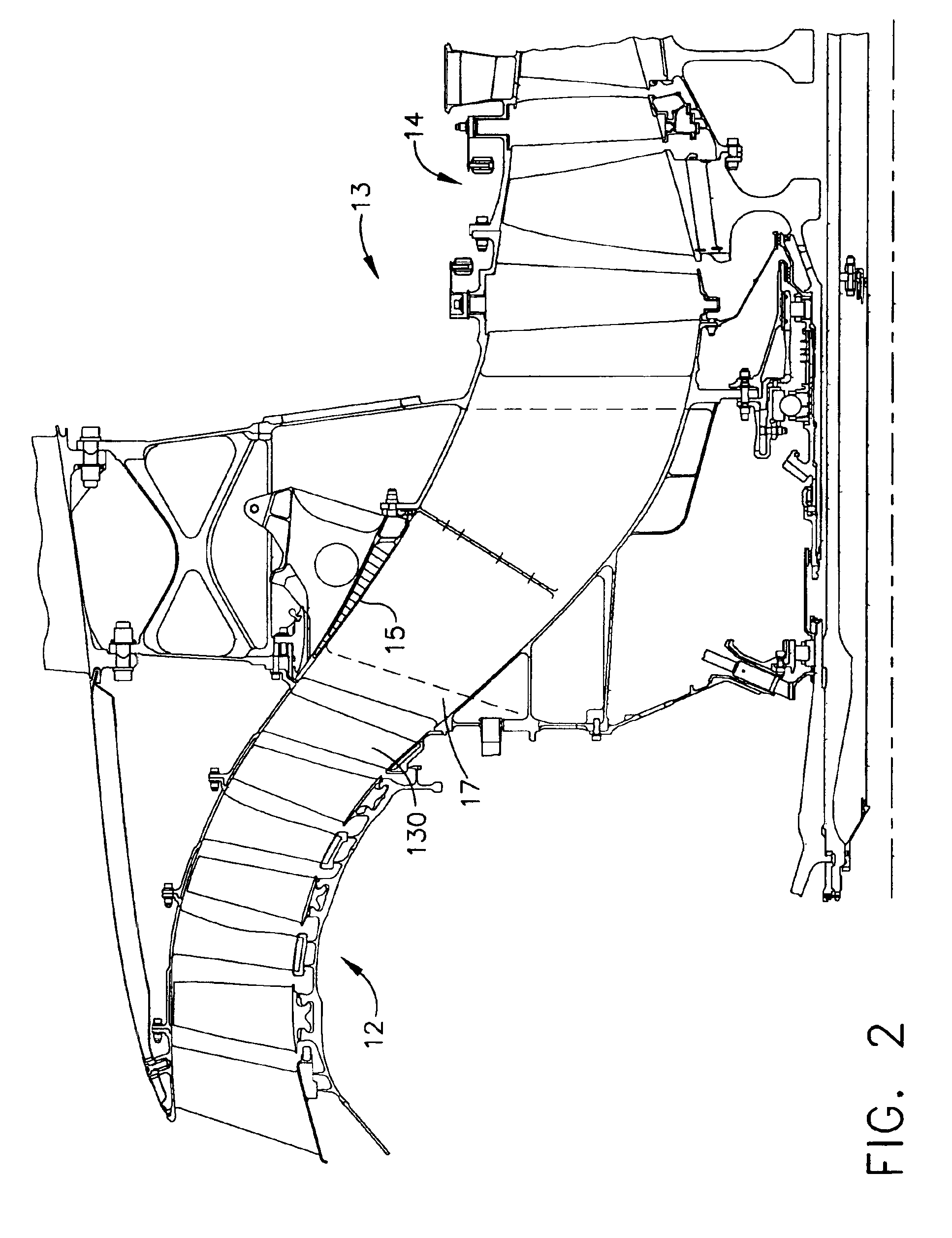
[0018]FIG. 2 shows a core duct 13 interconnecting low pressure compressor 12 and high pressure compressor 14. Core duct 13 includes a plurality of outlet guide vanes 130, a variable bleed valve door 15 through which bleed air is extracted from the gas path and a plurality of circumferentially spaced support struts 17.

[0019]In operation, air flows through low pressure compressor 12 from an upstream side 32 of engine 10 and compressed air is supplied ...


PUM

PropertyMeasurementUnit
angleaaaaaaaaaa
speedsaaaaaaaaaa
combustion gasesaaaaaaaaaa

Abstract

A method of assembling a gas turbine engine includes coupling an inner engine casing to an outer engine casing such that an annular flow path is defined therebetween, coupling a plurality of circumferentially-spaced support struts between the inner and outer casings, and coupling a plurality of circumferentially-spaced outlet guide vanes within the flow path upstream from the support struts, such that a first circumferential spacing is defined between a first guide vane and a second guide vane, and a second circumferential spacing is defined between the second guide vane and a third guide vane. The guide vanes are arranged such that the second guide vane is between the first and third guide vanes and the second circumferential spacing is different from the first circumferential spacing.

Description

BACKGROUND OF THE INVENTION[0001]This invention relates generally to gas turbine engines, and more specifically to guide vane assemblies used with gas turbine engines.[0002]Gas turbine engines typically include a compression system, which may consist of a single compressor or multiple compressors rotating at different speeds, for compressing a working fluid, such as air. The compressed air is channeled into a combustor wherein it is mixed with fuel and ignited to generate combustion gases which are channeled to a turbine. The turbine extracts energy from the combustion gasses to power the compressor, as well as to produce useful work to propel an aircraft in flight, or power a load, such as an electrical generator or a ship propeller.[0003]Many known compressors include an outlet guide vane assembly. Outlet guide vanes have airfoil-like cross sections. Known outlet guide vane (OGV) assemblies include a plurality of circumferentially spaced vanes that are spaced substantially uniform...

Claims


Application Information

Patent Timeline
Patent Type & Authority Patents(United States)
IPC IPC(8): F01D9/04F01D5/26F01D5/12F04D29/40F04D29/66F04D29/56
CPCF01D5/26F01D9/041F04D29/668F04D29/666F04D29/544Y10T29/49323Y02T50/671F05D2260/961Y02T50/60
Inventor LIU, HSIN-TUANBAILEY, WILLIAM ANDREWNIEDERMEIER, JOHN DOANE
Owner GENERAL ELECTRIC CO
Why Eureka
Try Eureka