Device in connection with pacers

a technology of a device and a connector, applied in the field of connectors, can solve the problems of difficult handling of screws, and achieve the effect of easy removal of the male connector parts

Inactive Publication Date: 2005-06-14
ST JUDE MEDICAL
View PDF5 Cites 7 Cited by
  • Summary
  • Abstract
  • Description
  • Claims
  • Application Information

AI Technical Summary

Benefits of technology

[0009]The primary object of the invention is to provide a connector locking part of the kind described above, which can be used with standard male connector parts, which involves a positive locking effect and which does not need any lateral openings in the connector housing or the pacemaker housing. At the same time, it should be possible to easily remove the male connector part without any need of manual o

Problems solved by technology

While these setscrews generally have a good fixing effect, the

Method used


Image

  • Device in connection with pacers
  • Device in connection with pacers
  • Device in connection with pacers

Examples


Embodiment Construction

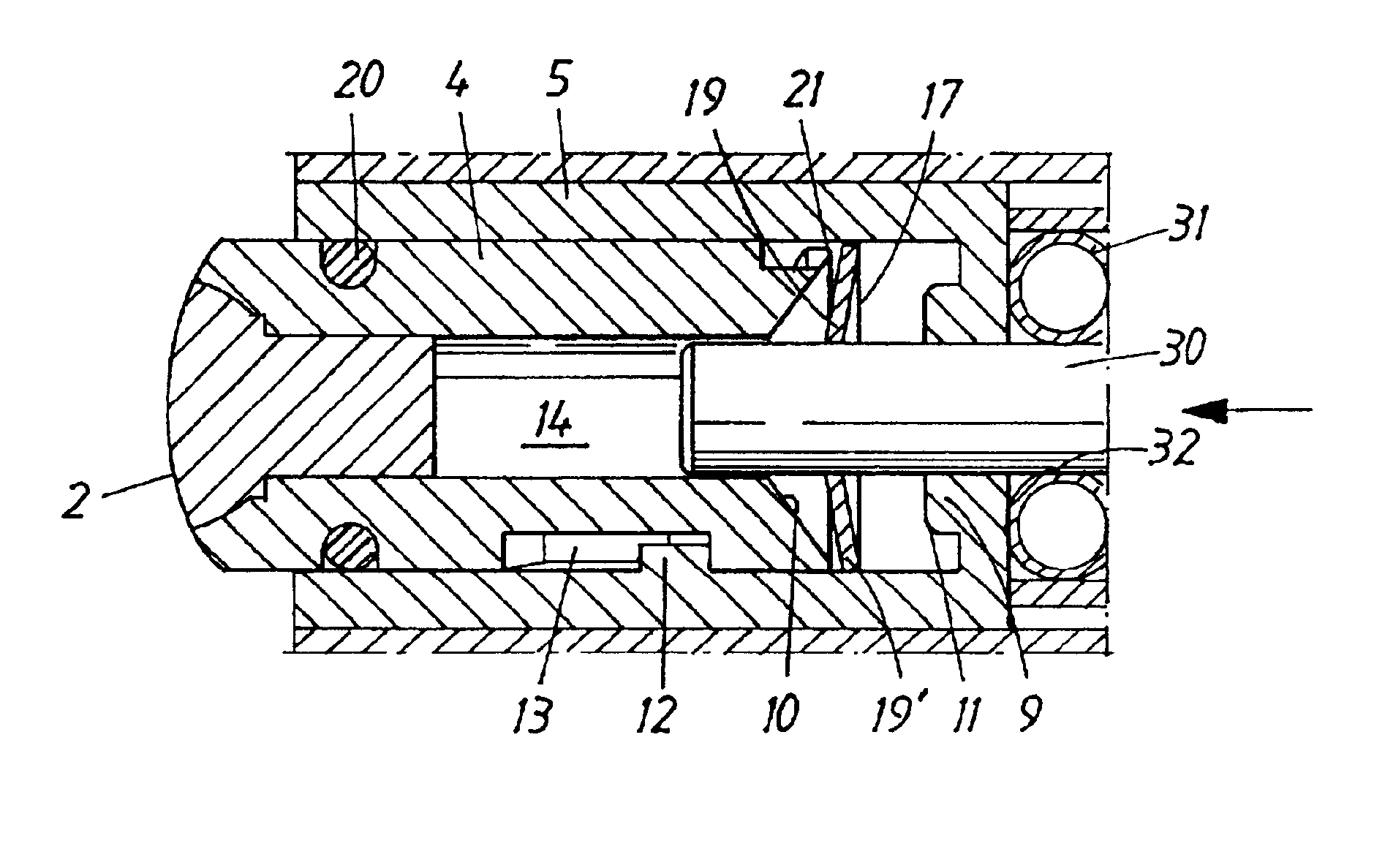
[0016]In the description below, “longitudinal” relates to the longitudinal direction of the female connector part and “outer end” relates to the end of the locking device accessible from the outside. It should be noted that all reference signs are not repeated throughout all drawings.

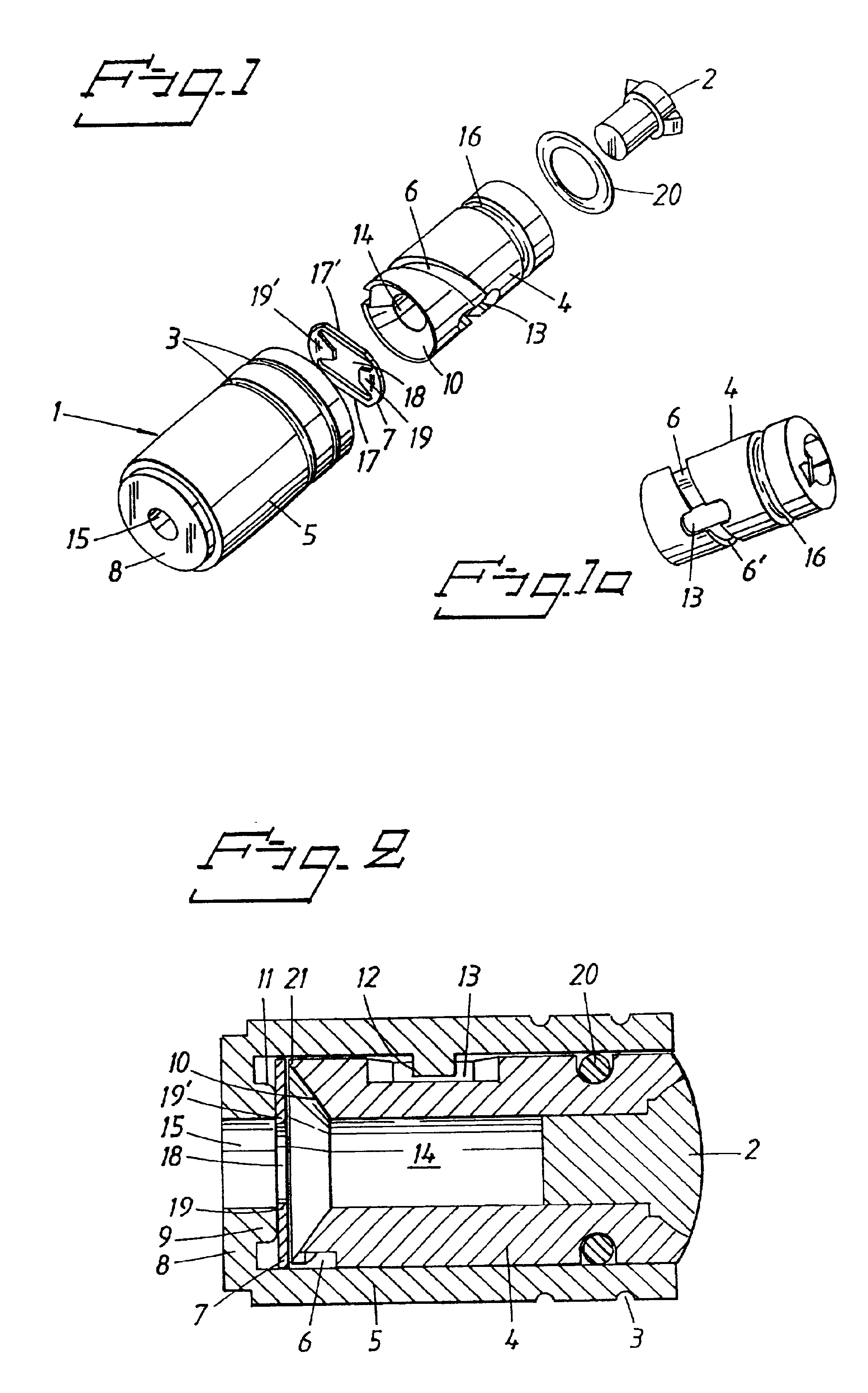
[0017]The component parts of a locking part 1 for a female connector according to a preferred embodiment are shown in an exploded view in FIG. 1. The locking part comprises a hollow cylindrical part 5 with an end wall 8 in which a central opening 15 is located. The opening 15 is dimensioned to receive the contact pin of a standard male connector. The outside of the cylindrical part is provided with circumferential grooves 3 serving as space for excess glue when the cylindrical part is glued into a female connector part.

[0018]The locking device further comprises a locking washer 7 with a central opening 18. Two locking tongues 19, 19′ are located on opposite sides of the opening 18 and extend into the op...


PUM


Abstract

The invention relates to a locking device (1) for a female connector part for cooperation with an elongate, male connector part (30), said female connector part being intended for use in a pacer housing. Said female connector part comprises a longitudinal bore defining a longitudinal space for said locking device. Said locking device comprises one or several tongues (19, 19′) being swingable between two positions, a first position in which the tips of the tongues (19, 19′) can engage said male elongate connector part (30) and a second position in which the tips of the tongues (19, 19′) will not engage the male elongate connector part (30). Said tongues are biased towards said first position by means of a spring force. A pivot (9) is associated with each tongue and each tongue has a first part engaging said connector means (30) and being located on one side of said pivot and a second part being located on the other side of said pivot. Longitudinally acting means (4) are provided to act on said second part of said tongues (19, 19′) for actuating said tongues from said first position against said bias to said second position.

Description

BACKGROUND OF THE INVENTION[0001]1. Field of the Invention[0002]The present invention relates to a connector for connecting leads to a housing for an implantable pacer.[0003]2. Description of the Prior Art[0004]A pacer system normally comprises a pulse generator located in a pacer housing, leads and electrodes at the distal end of the leads. The proximal end of the leads is connected to the pacer housing by means of a releasable connector. The connector comprises a female connector part in the pacer housing. The proximal end of the lead normally is designed as a standardized male connector part and the female connector part normally is standardized to such an extent that it will receive this standardized male connector part. The most common way of fixing or locking the male connector part in the female connector part is to use set screws which are oriented in an orthogonal direction in relation to the male connector part and which are accessible from the outside of the pacer housing...

Claims


Application Information

Patent Timeline
IPC IPC(8): A61N1/372A61N1/375H01R4/48
CPCA61N1/3752H01R4/4818Y10S439/909H01R4/48185
Inventor HILL, ROLF
Owner ST JUDE MEDICAL
Why Eureka
Try Eureka