Ink cartridge and ink jet printer

Inactive Publication Date: 2005-06-21
SEIKO EPSON CORP
View PDF21 Cites 74 Cited by
  • Summary
  • Abstract
  • Description
  • Claims
  • Application Information

AI Technical Summary

Benefits of technology

[0050]According to this configuration, the ink cartridge having a low probability of use is provided with the waste-ink holding member, so that the capacity of the waste-ink holding member can be used effectively. Also, the volume of the ink cartridge placement section can be reduced and the ink jet printer can be miniaturized as compared with the case where every ink cartridge includes a waste-ink holding portion.
[0051]It is desirable that the waste-ink holding member have a holding capacity in the range of 1 to 1.3 times a capacity found by multiplying: (i) the volume of ink available to the ink jet head as the amount

Problems solved by technology

However, if two ink cartridges are placed in the ink jet printer, it becomes cumbersome to attach and detach the ink cartridges and the ink cartridge placement

Method used


Image

  • Ink cartridge and ink jet printer
  • Ink cartridge and ink jet printer
  • Ink cartridge and ink jet printer

Examples


first embodiment

having a Partition Plate

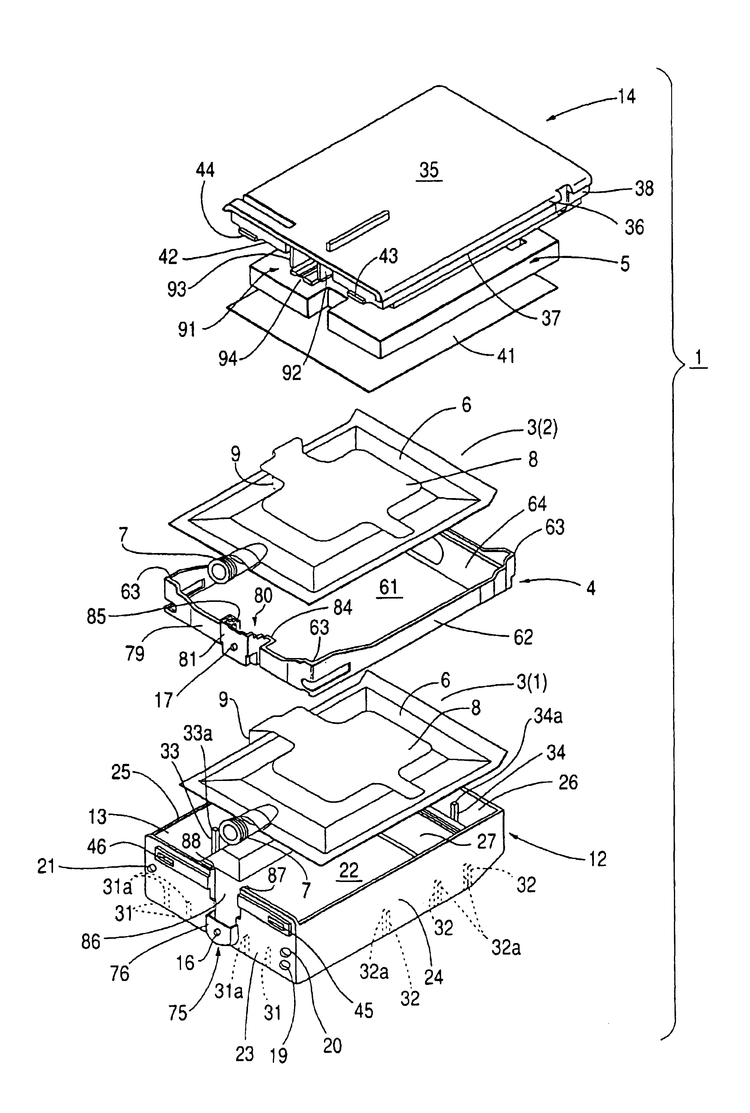
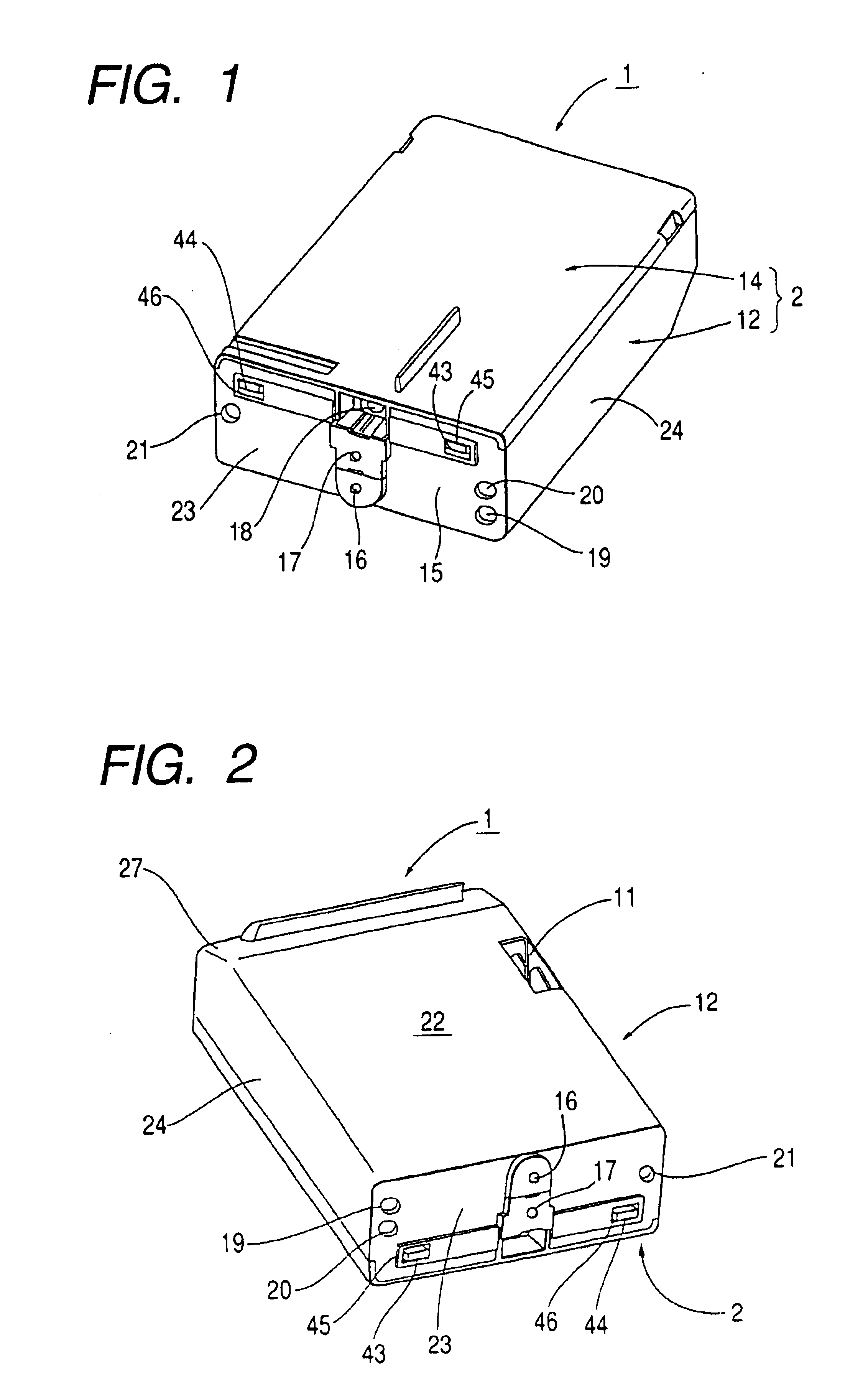
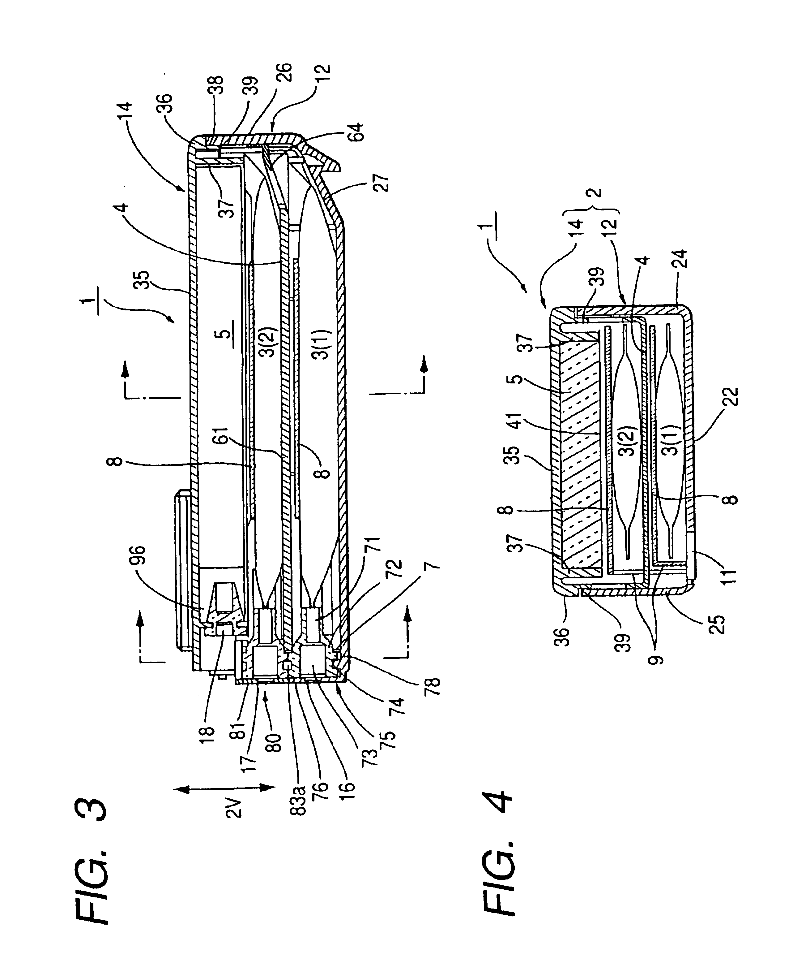
[0083]FIG. 1 is an external perspective view of an ink cartridge with a partition plate according to an embodiment of the invention when the ink cartridge is viewed from the top. FIG. 2 is an external perspective view of the ink cartridge when the ink cartridge is viewed from the bottom. FIG. 3 is a longitudinal sectional view of the ink cartridge. FIG. 4 is a transverse sectional view of the ink cartridge. FIG. 5 is an exploded perspective view of the ink cartridge. FIG. 6 is a fragmentary sectional view showing a joint structure of a case main body and a case lid of a cartridge case. FIG. 7 is a schematic representation showing a structure by which ink outlets of ink bags are fixedly housed.

[0084]As shown in the figures, an ink cartridge 1 comprises a cartridge case 2 shaped like a fiat rectangular parallelepiped, first and second ink bags 3(1) and 3(2) housed in the cartridge case 2, a partition plate 4 placed between the ink bags, and a waste-ink absorpti...

second embodiment

having a Partition Plate

[0124]The above-described ink cartridge 1, having a partition plate, comprises two ink bags and one partition plate placed therebetween. However, of course the invention can also be applied to an ink cartridge comprising three or more ink bags and partition plates each placed between two ink bags.

[0125]FIGS. 9 and 10, respectively, are an exploded perspective view and a transverse sectional view showing a second embodiment of an ink cartridge comprising three ink bags and two partition plates each for partitioning the ink bags.

[0126]As shown in the figures, an ink cartridge 100 has a case main body 112, first, second, and third ink bags 103(1), 103(2), and 103(3) housed in the case main body 112, two partition plates 104(1) and 104(2) each placed between two ink bags, a waste-ink absorption material 105, and a case lid 114.

[0127]The case main body 112 and the case lid 114 are joined according to a snap fit structure as described above in connection with the i...

fifth embodiment

Cartridge

[0176]Next, an ink cartridge of another configuration incorporating the present invention will be discussed. The ink cartridge described below is a split-type ink cartridge having a structure that can be split up and down.

[0177]FIG. 18 is an external perspective view of the split-type ink cartridge of this embodiment as the ink cartridge is viewed from the top, FIG. 19 is an external perspective view of the split-type ink cartridge of this embodiment as the ink cartridge is viewed from the bottom, FIG. 20 is a longitudinal sectional view of the split-type ink cartridge, and FIG. 21 is an exploded perspective view of the split-type ink cartridge.

[0178]Referring to the figures, an ink cartridge 400 includes a first ink cartridge 500 and a second ink cartridge 600. The ink cartridge 500 is shaped like a flat rectangular parallelepiped in which a first ink bag 401(1) and a waste-ink absorption material 402 are housed. Similarly, the second ink cartridge 600 is shaped like a fla...


PUM


Abstract

An ink cartridge, for an ink jet printer, having a cartridge case, first and second ink bags housed in the cartridge case, and a partition plate placed between the ink bags. The partition plate is dropped into a case main body of the cartridge case through an upper opening of the case main body. When a case lid is attached to the case main body, the partition plate is sandwiched between rib upper end faces of the case main body and an outer frame end face of the case lid so that the position of the partition plate is fixed. Ink outlet parts, of the ink bags, are overlaid on each other in a case thickness direction so that they are in contact with each other without intervention of the partition plate. Therefore, the ink cartridge is miniaturized and can be easily disassembled when it is recycled.

Description

BACKGROUND OF THE INVENTION[0001]1. Field of the Invention[0002]This invention relates to an ink cartridge used as an ink supply source of an ink jet printer and, in particular, to an ink cartridge comprising a configuration adequate for recycling and a configuration adequate for miniaturization. The present invention also relates to an ink jet printer using the above-described ink cartridge.[0003]2. Description of the Related Art[0004]A known ink supply mechanism of an ink jet printer is as follows An ink supply needle is placed in an ink cartridge placement part formed in an ink jet printer and, if an ink cartridge is placed so that the ink supply needle is inserted into an ink outlet formed in the ink cartridge, ink stored in the ink cartridge can be supplied to an ink jet head of the ink jet printer.[0005]The ink cartridges used with such an ink jet printer are disclosed in JP-A-63-116833, JP-A-5-162333, JP-A-11-70672, etc. For example, the ink cartridge disclosed in JP-A-11-706...

Claims


Application Information

Patent Timeline
IPC IPC(8): B41J2/175
CPCB41J2/175
Inventor NAKAZAWA, CHIYOSHIGEYAMADA, MANABUSUZUKI, TOMOJIYOKOYAMA, KAZUYUKI
Owner SEIKO EPSON CORP
Why Eureka
Try Eureka