Flourescent light fixture

a fluorescent light and fixture technology, applied in the field of light fixtures, can solve the problems of time-consuming, cumbersome and costly installation of retrofit kits, and inability to meet the requirements of the application, and achieve the effects of reducing the cost of retrofit kits

Inactive Publication Date: 2005-06-21
RETRO LIGHT
View PDF3 Cites 118 Cited by
  • Summary
  • Abstract
  • Description
  • Claims
  • Application Information

AI Technical Summary

Benefits of technology

[0027]An advantage of the present invention is that the reflector and the socket plates form the structural framework for the fluorescent light fixture. A separate housing is unnecessary. Another advantage of the present invention is that the fluorescent light fixture can expand and contract in length to allow ease of installation of the fluorescent light fixture into an existing fixture shell. Yet another advantage of the present invention is that fluorescent light fixture can be temporarily secured within an existing fixture shell using the attachment thereby freeing the installer from having to hold the fluorescent light fixture in place during installation or fastening or securing.

Problems solved by technology

However, given the number of fixtures that would ordinarily require replacement, this solution may not be cost effective.
However, these retrofit kits suffer from a variety of problems.
The installation of retrofit kits can be time consuming, cumbersome and costly.
Using currently available retrofit kits, it typically takes 30 minutes to convert a single light fixture.
This awkwardness increases the effort and skill required for the installation and the inspection of individual components and also contributes to physical fatigue.
There are also safety concerns arising from working on a ladder for a significant period of time.
These factors limit the number of retrofit kits which can be installed at any one time by an installer.

Method used


Image

  • Flourescent light fixture
  • Flourescent light fixture
  • Flourescent light fixture

Examples


Embodiment Construction

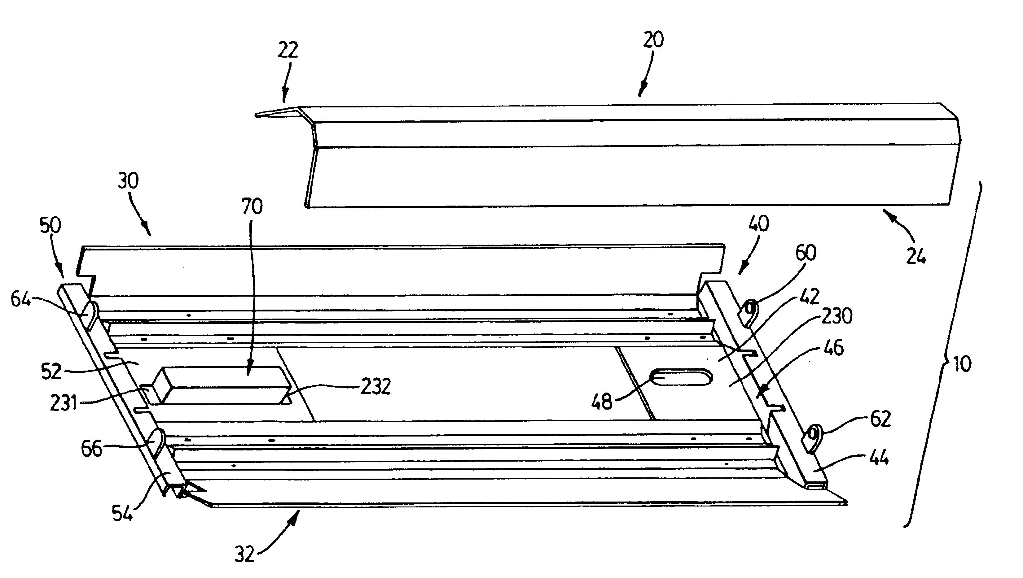
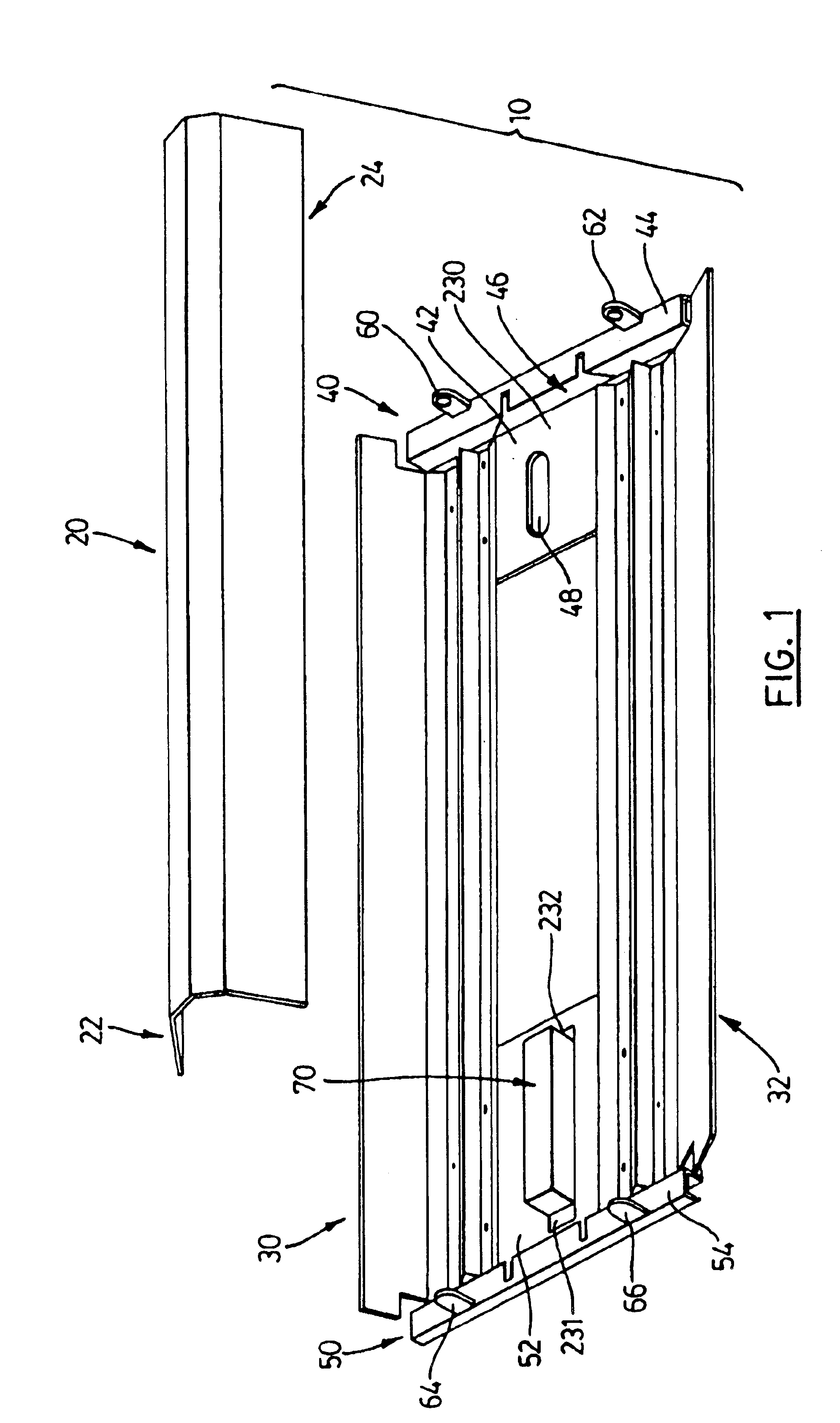
[0046]The invention is a fluorescent light fixture retrofit insert (hereinafter “retrofit”) related to adapting older model fluorescent lighting fixtures to use high efficiency fluorescent lamps and ballasts.

[0047]As shown in FIG. 1, the retrofit 10 comprises a downwardly facing ballast cover 20 and reflectors 30 and 32 on either side thereof. The ballast cover 20 and reflectors 30 and 32 are mounted on a first socket plate 40 and a second socket plate 50 located at opposite ends of the ballast cover 20 and reflectors 30 and 32. As will be understood by those knowledgeable in the art, the socket plates 40 and 50 and the reflectors 30 and 32 are typically spaced apart to fit a 2′×4′ fluorescent lighting fixture shell for T8 lamps. The retrofit can be adapted to fit lighting fixture sizes of varying sizes. For example, 8′ T12 lamps can be replaced by two sets of 4′ T8 lamps. Other examples include 2′, 3′ and 4′ fixture lengths.

[0048]In this embodiment, the retrofit 10 comprises a rect...


PUM


Abstract

A fluorescent light fixture is provided for retrofitting light fixtures utilizing conventional fluorescent lamps into light fixtures utilizing energy efficient fluorescent lamps. The fluorescent light fixture is a single unit comprising a reflector, socket plates at each end, lamp sockets, ballast, ballast cover and wiring. The reflector may be slidably mounted onto the socket plates to allow the retrofit to expand and contract. The fluorescent light fixture may include a attachment which temporarily secures the fluorescent light fixture within a light fixture shell.

Description

FIELD OF THE INVENTION[0001]This invention relates to light fixtures and more particularly to a fluorescent light fixture which retrofits a fixture which uses conventional fluorescent lamps with a fixture which uses high energy efficient fluorescent lamps and ballasts.BACKGROUND OF THE INVENTION[0002]Fluorescent light fixtures are widely used in industrial, commercial, retail, institutional and office applications. Older model light fixtures generally employ T12 fluorescent lamps and magnetic ballasts whereas newer models employ high efficiency T8 fluorescent lamps and electronic ballasts. The use of T8 technology represents a significant improvement over T12 technology in terms of both energy efficiency (up to 40% increase) and illumination efficiency (up to 25% increase). T8 fluorescent lamps also last 20% longer compared to T12 fluorescent lamps.[0003]One way to reduce the high operating and maintenance costs associated with older model fluorescent light fixtures is simply to rep...

Claims


Application Information

Patent Timeline
Patent Type & Authority Patents(United States)
IPC IPC(8): F21V15/01F21V17/06F21V19/00F21V15/00F21V17/00F21V17/10F21V23/02F21V17/12
CPCF21V15/01F21V17/06F21V17/104F21V19/008F21V23/02F21V17/101F21V17/105F21Y2113/00Y02B20/386F21Y2103/00F21V17/12Y02B20/30
Inventor SCHULTZ, MICHAEL
Owner RETRO LIGHT
Why Eureka
Try Eureka