Plug connector, consisting of a plug-in jack and a plug part

a plug-in jack and plug-in technology, which is applied in the direction of coupling device connection, coupling part engagement/disengagement, incorrect coupling prevention, etc., can solve the problems of deformation and stress on the soldering point of the contacts, and the inability of the plug-in card to guide,

Inactive Publication Date: 2005-06-21
BERGLIN CORP OF WASHINGTON
View PDF18 Cites 22 Cited by
  • Summary
  • Abstract
  • Description
  • Claims
  • Application Information

AI Technical Summary

Benefits of technology

[0004]Thus, it is the object underlying the invention to provide a plug connector in which the contacts are not exposed to high mechanical loads during insertion of t

Problems solved by technology

There arises a problem in that the plug-in card cannot be guided so precisely in the housing that it can be inserted

Method used


Image

  • Plug connector, consisting of a plug-in jack and a plug part
  • Plug connector, consisting of a plug-in jack and a plug part
  • Plug connector, consisting of a plug-in jack and a plug part

Examples


Embodiment Construction

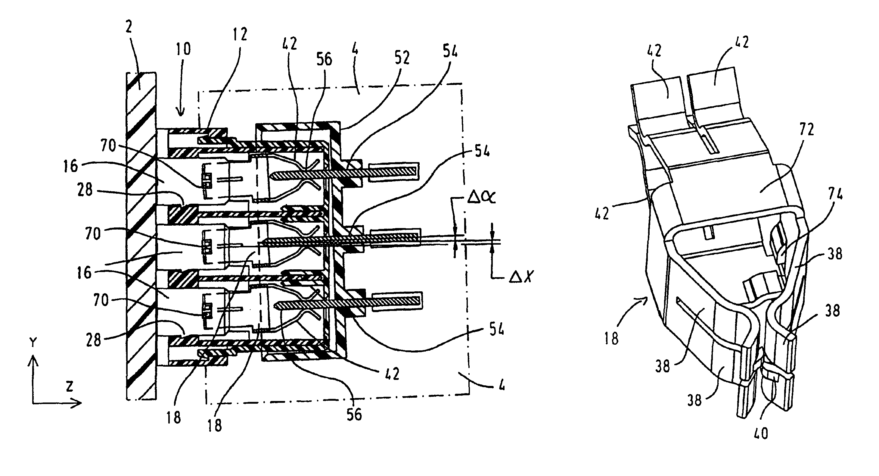
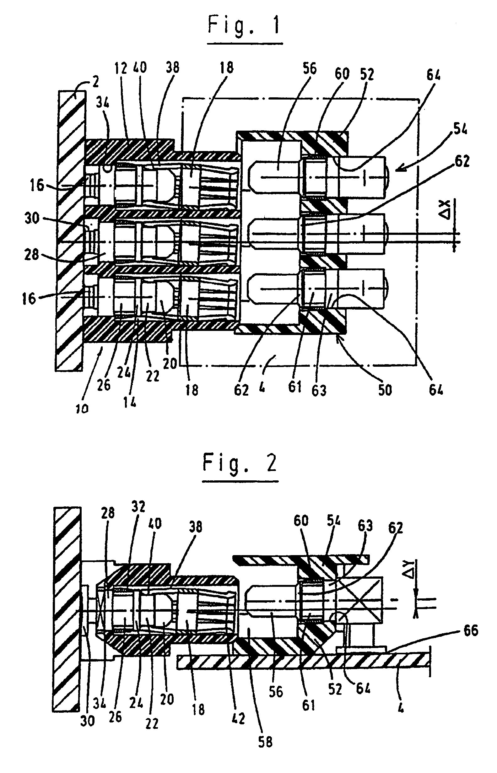
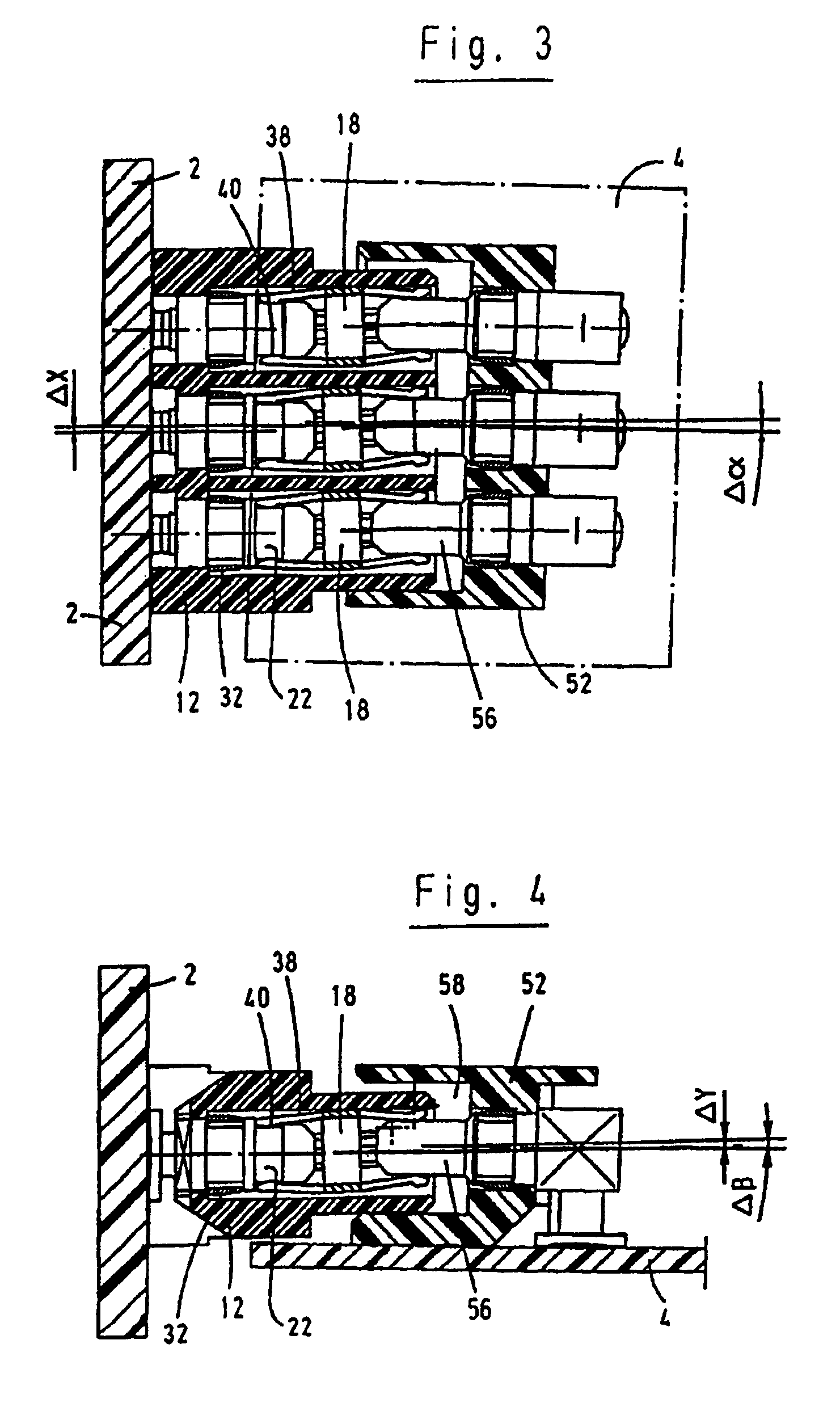
[0028]FIGS. 1 and 2 show a plug connector according to a first embodiment, which consists of plug-in jack 10 and plug part 50. This concerns a so-called backplane plug connector in which the plug-in jack 10 is mounted on a motherboard 2 configured as a circuit board, and the plug part 50 is mounted on a plug-in card 4 equally configured as a circuit board. Motherboard 2 is part of an electric or electronic device in which the plug-in card 4 is inserted. The guide for plug-in card 4 in the device housing is not shown here. Of course, the structure of the plug connector may also be used for other fields of application.

[0029]The plug-in jack 10 comprises an electrically insulating jack housing 12 in which three cylindrical contact chambers are formed. In each contact chamber, there is disposed a jack contact 14 consisting of a retaining part 16 and a jack 18. The retaining part comprises a head portion 20, an annular groove 22, a collar 24 adjoining the annular groove, an anchor groove...


PUM


Abstract

The invention relates to a plug-in jack comprising an insulating jack housing in which at least one jack contact is accommodated. The jack contact consists of a retaining part and a jack, the jack being mounted on the retaining part so as to be pivotable by a limited angle. The invention further relates to a plug part having an insulating plug housing in which there is accommodated at least one plug contact provided for engaging into the jack contact of the plug-in jack.

Description

CROSS-REFERENCE TO RELATED APPLICATION[0001]This application is a divisional of U.S. application Ser. No. 10 / 067,656, filed Feb. 4, 2002 now U.S. Pat. No. 6,773,285, issued Aug. 10, 2004.TECHNICAL FIELD[0002]The invention relates to a plug connector consisting of a plug-in jack and a plug part provided for insertion into the plug-in jack. More particularly, the invention relates to a so-called back-panel plug connector in which one of the two plug connector parts is mounted on a back-panel circuit board firmly mounted in a housing of an electrical device, the so-called motherboard, and the other part of the plug connector is mounted on a pluggable circuit board, the so-called plug-in card. When the plug-in card is inserted into the housing, the contacts of the plug-in jack and of the plug part, respectively, engage into the contacts of the other part so that the plug-in card is connected to the motherboard.BACKGROUND OF THE INVENTION[0003]There arises a problem in that the plug-in c...

Claims


Application Information

Patent Timeline
IPC IPC(8): H01R13/631H01R13/62
CPCH01R13/6315H01R13/62
Inventor BERNAT, JEAN FRANCOISDE VANSSAY, JEAN-MERRI
Owner BERGLIN CORP OF WASHINGTON
Why Eureka
Try Eureka