Anisotropic scattering sheet and its use

a technology of anisotropic scattering and diffusing sheets, which is applied in the direction of mechanical equipment, instruments, transportation and packaging, etc., can solve the problems of unduly lowering of the luminance in a certain direction (the axis-direction of the fluorescent tube), difficult to uniformly illuminate the display panel with the high luminance, and unduly lowering of the luminance, so as to inhibit the deterioration of the luminance

Inactive Publication Date: 2005-06-21
DAICEL CHEM IND LTD
View PDF12 Cites 15 Cited by
  • Summary
  • Abstract
  • Description
  • Claims
  • Application Information

AI Technical Summary

Benefits of technology

[0024]The inventors of the present invention did much research to accomplish the above objects and found that: by disposing an anisotropic scattering or diffusing sheet between a light guide member and a display panel, a transmission light through a light-scattering sheet can be scattered anisotropically to illuminate a display panel uniformly; and that use of a film having anisotropic light-scattering property in combination with a prism sheet can inhibit the deterioration of the luminance depending on an angle of a display surface of a transmittable liquid crystal display apparatus (e.g., the luminance of one-direction such as a horizontal direction). The present invention has been developed on the basis of the above findings.

Problems solved by technology

However, even when such a diffusing film is used, it is inevitable due to its isotropy of light diffusing that the luminance in a certain direction (the axis-direction of the fluorescent tube) is unduly lowered.
As a result, it is unable to illuminate the display panel uniformly with the high luminance.
Therefore, it is difficult to illuminate the display panel uniformly.
Since a plurality of prism sheets and a plurality of diffusers are required for such a backlight unit, its structure is complicated and its luminance is lowered.
Moreover, even when the above backlight unit is employed, its luminance distribution is not still uniform.
Thus, although an emission distribution (luminance distribution) in the longitudinal direction (X-axis direction) of the fluorescent tube (cold cathode tube) is relatively uniform, the emission distribution (luminance distribution) in the Y-axis direction perpendicular to the X-axis direction of the fluorescent tube has a streak-like directionality (linear dark areas) and is not still uniform.
When such a backlight unit is used, a display panel can be illuminated by focusing a diffused light with use of a prism sheet, and in contrast to the backlight unit or component of FIG. 8, the emission distribution may appear uniform over the surface but a detailed observation of the emission distribution reveals that the distribution is still not as uniform as desired.
Such display apparatus restricts an angle of vision (visual angle or viewing angle) for a user of the display apparatus, and therefore, the user can not recognize the display of the display surface visually in a wide angle.
Thus the display apparatus is inconvenient and effects a sense of fatigue.
However, in such a diffusing sheet, the luminance is extremely deteriorated.
However, in a display apparatus with the use of a tubular light source having anisotropy in an emission distribution (luminance distribution), it is difficult to illuminate a display panel with uniform luminance even if using these films or sheets.

Method used


Image

  • Anisotropic scattering sheet and its use
  • Anisotropic scattering sheet and its use
  • Anisotropic scattering sheet and its use

Examples


example 1

[0172]As the continuous phase resin, 60 parts by weight of crystalline polypropylene-series resin PP (manufactured by Grand Polymer Co.; F109BA, refractive index 1.503); as the dispersed phase resin, 36 parts by weight of noncrystalline copolyester-series resin (PET-G, manufactured by Eastman Chemical Company; Eastar PETG GN071, refractive index 1.567); and as the compatibilizing agent, 4 parts by weight of epoxidized diene-series block copolymer resin (manufactured by Daicel Chemical Industries, Ltd.; Epofriend AT202; styrene / butadiene 70 / 30 (by weight), epoxy equivalent 750, refractive index about 1.57) were used. The refractive index differential between the continuous phase resin and the dispersed phase resin was 0.064.

[0173]The above continuous phase resin and dispersed phase resin were dried at 70° C. for about 4 hours, and kneaded these resins in a Banbury mixer. Using an extruder of multi-layered type, the kneaded product for forming a center or intermediate layer and the co...

example 2

[0178]The above continuous phase resin and dispersed phase resin were melt-molded in the same manner as Example 1, and extruded from a T-die at a draw ratio of about 6 onto a cooling drum having a surface temperature of 25° C. The total thickness of the obtained sheet was 125 μm, and an anisotropic scattering sheet was composed of a light-scattering layer as the center layer having a thickness of about 100 μm and surface layers formed by a continuous phase resin on both sides the scattering layer and each having about 12.5 μm thickness.

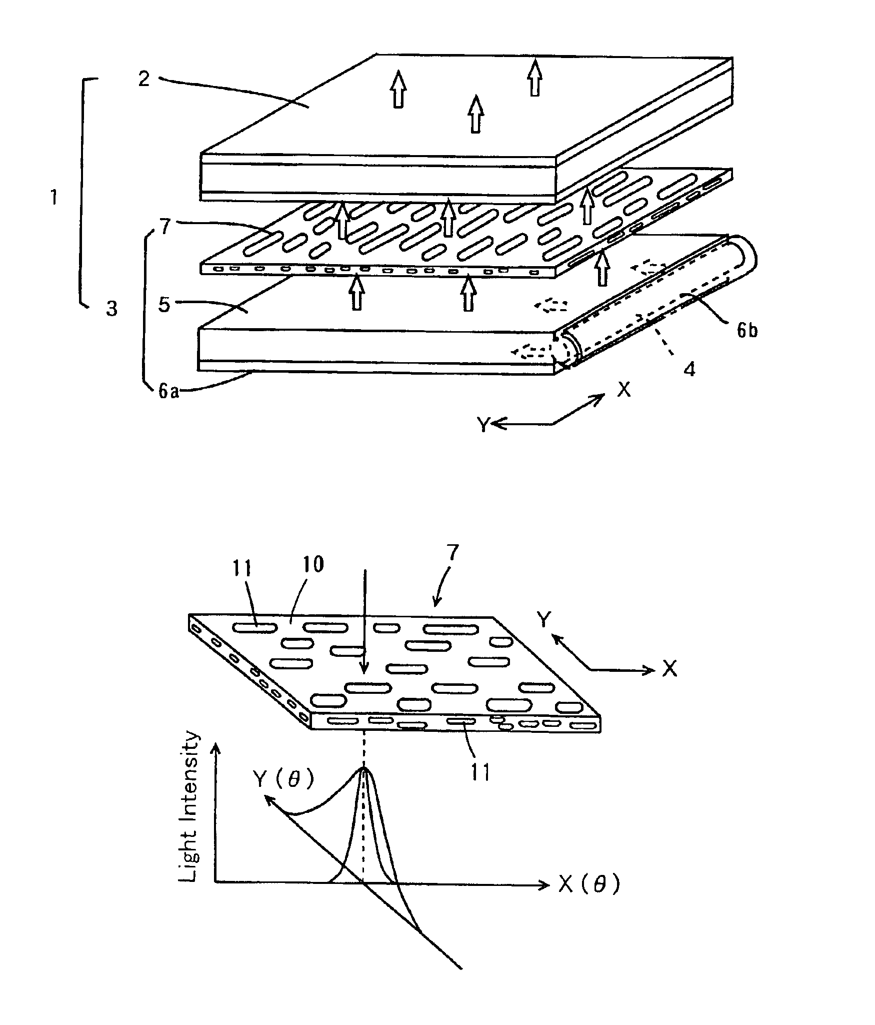
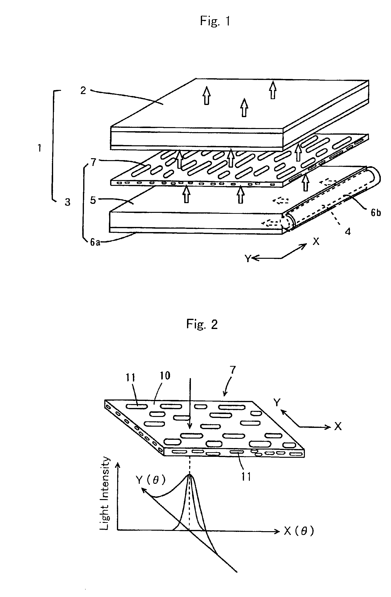
[0179]Observation of the micro-structure of thus obtained sheet in the same manner as Example 1 revealed that the dispersed phase of the center layer showed like an elongated fiber, with a mean major axis dimension of about 15 μm and a mean minor axis dimension of about 2 μm. Measurement of the light-scattering characteristic of thus obtained anisotropic scattering sheet revealed that Fy(4°) / Fx(4°) was 2.4, with respect to the scattering in Y-axial di...

example 4

[0181]As the continuous phase resin, 80 parts by weight of a crystalline polypropylene-series resin PP (manufactured by Grand Polymer Co.; F133, refractive index 1.503); as the dispersed phase resin, 18 parts by weight of a polystyrenic resin GPPS (general-purpose polystyrenic resin, manufactured by Daicel Chemical Industries, Ltd., GPPS #30, refractive index 1.589); and as the compatibilizing agent, 2 parts by weight of an epoxidized diene-series block copolymer resin (manufactured by Daicel Chemical Industries, Ltd.; Epofriend AT202; styrene / butadiene=70 / 30 (by weight), epoxy equivalent 750, refractive index about 1.57) were used. The refractive index differential between the continuous phase resin and the dispersed phase resin was 0.086.

[0182]A sheet having a three-layered structure was produced in the same manner as in Example 1. Observation of the micro-structure of the sheet in the same manner as in Example 1 showed that the dispersed phase of the center layer had an elongated...


PUM

PropertyMeasurementUnit
light-scattering angleaaaaaaaaaa
mean aspect ratioaaaaaaaaaa
total light transmittanceaaaaaaaaaa

Abstract

An anisotropic scattering sheet is adapted to scatter an incident light in a light-advancing direction and has a light-scattering characteristic F(θ) that satisfies the following expression representing a relation between a light-scattering angle θ and a scattered light intensity F over a range of θ=4 to 30°: Fy(θ) / Fx(θ)>2, wherein Fx(θ) represents the light-scattering characteristic in a direction of a X-axis and Fy(θ) represents a light-scattering characteristic in a Y-axial direction which is perpendicular to the X-axial direction.

Description

[0001]This application is the national phase under 35 U.S.C. § 371 of PCT International Application No. PCT / JP01 / 09134 which has an International filing date of Oct. 18, 2001, which designated the United States of America.TECHNICAL FIELD[0002]The present invention relates to an anisotropic scattering or diffusing sheet which is capable of illuminating a display unit of a display apparatus (in particular, a transmittable (transmission type) liquid crystal display apparatus) uniformly and inhibiting a change of the luminance even when a visual angle on or to a display surface changes, a plane light source unit using the sheet (a backlight unit or device), and a display apparatus using the unit (particularly, a transmittable display apparatus such as a transmittable liquid crystal display apparatus). Specifically, the present invention relates to an anisotropic scattering or diffusing sheet which is capable of inhibiting a change of the luminance even when a visual angle somewhat chang...

Claims


Application Information

Patent Timeline
Patent Type & Authority Patents(United States)
IPC IPC(8): F21V8/00G02F1/1335G02F1/13G02B5/02G02B6/00
CPCG02B5/0242G02B5/0257G02B5/0278G02B6/0053G02F1/133504G02B6/0051G02B6/0031Y10T428/10G02B6/0071C09K2323/00G02B5/02
Inventor HIRAISHI, MASANORIOHNISHI, MASANARI
Owner DAICEL CHEM IND LTD
Why Eureka
Try Eureka