Plasma display unit

a technology of display unit and plasma, which is applied in the direction of discharge tube luminescnet screen, gas-filled discharge tube, address electrode, etc., can solve the problems of increased surface area of phosphor, increased positive charge, and reduced oxygen defects near the ba--o layer. , the effect of increasing the positive charge and significantly increasing the positive charg

Inactive Publication Date: 2004-09-23
PANASONIC CORP
View PDF3 Cites 0 Cited by
  • Summary
  • Abstract
  • Description
  • Claims
  • Application Information

AI Technical Summary

Benefits of technology

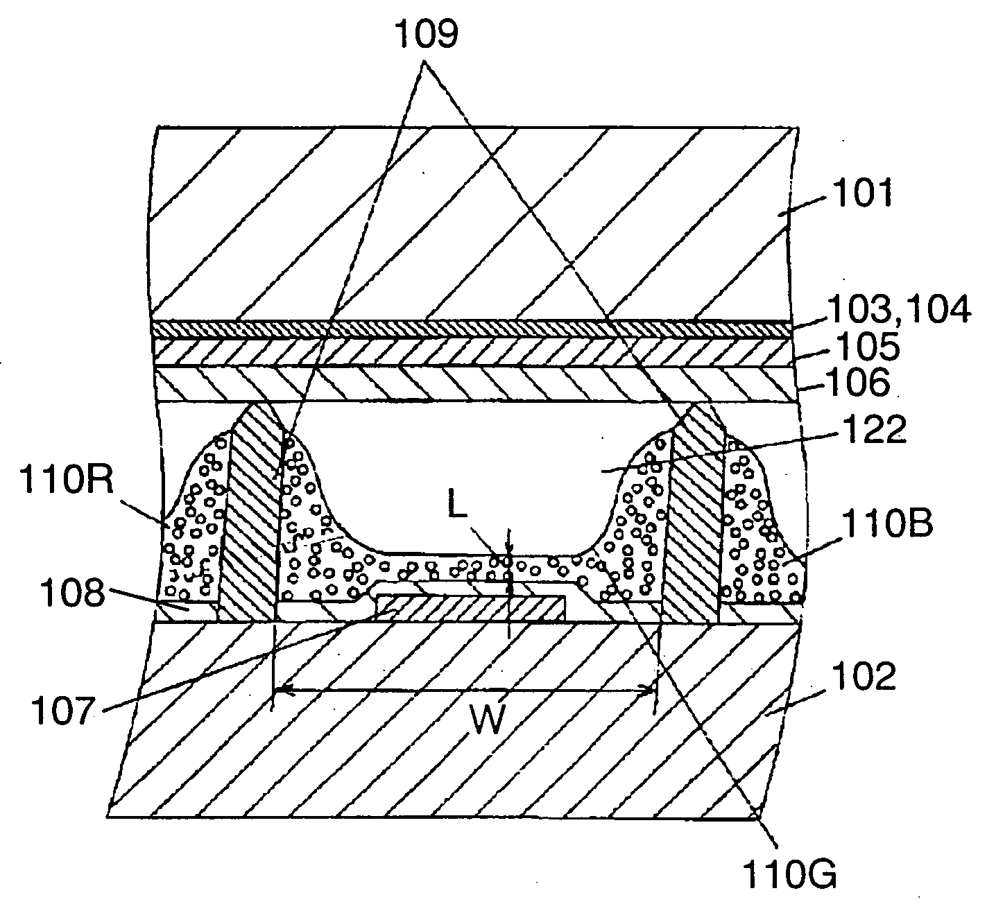
[0011] In this plasma display device, trivalent La is present in a greater proportion in the crystal of (Ba,Sr)EuMgAl.sub.10O.sub.17 used for the blue phosphor, and thus the positive charge significantly increases. To counterbalance this significantly increased positive charge (to compensate for the charge), oxygen with a negative charge fills the oxygen defects near Ba element. As a result, the oxygen defects near the Ba--O layer can be reduced, preventing luminance deterioration during manufacturing processes and deterioration due to 147-nm ultraviolet rays.

Problems solved by technology

However, in practice, the use of phosphor particles with a smaller diameter increases the surface area of the phosphor and therefore of the risk of defects in the phosphor.
In addition, it is known that ultraviolet rays with wavelength 147 nm generated by discharge when driving the panel also cause defects in the phosphor (e.g.
In a conventional blue phosphor, the occurrence of these defects is believed to cause degradation of luminance.
More specifically, defects caused by ions generated when driving the panel that collide with the phosphor, and defects caused by ultraviolet rays of wavelength 147 nm are thought to degrade luminance.

Method used


Image

  • Plasma display unit
  • Plasma display unit
  • Plasma display unit

Examples


experiment 1

[0086] (Experiment 1)

[0087] Luminance and change in luminance of the blue phosphor of Specimens 1 to 9 and Comparisons 10 and 11 are measured after the phosphor-firing step (at 520.degree. C. for 20 hr), and then irradiation of 147 nm ultraviolet rays (using HD0012 excimer lamp, Ushio Corporation) for 100 hours in the rear panel manufacturing process.

experiment 2

[0088] (Experiment 2)

[0089] Luminance and change in deterioration of luminance of the blue phosphor are measured while lighting the panel with each color. Discharge maintenance pulses of 200 V and 100 kHz are applied continuously to the plasma display device for 100 hours, and the panel luminance is measured before and after applying the pulses. The rate of change in deterioration of luminance [(luminance before pulse application-luminance after pulse application) / luminance before pulse application.times.100]] is calculated from the measured values.

experiment 3

[0090] (Experiment 3)

[0091] Luminance when only blue is lighted over the entire face of the panel is measured while applying 180 V and 50 kHz to the display electrodes of the plasma display device.

[0092] An address error at address discharge of the plasma display device is visually determined by whether flickering exists in the displayed image. If there is flickering even at one point, it is determined as the presence of an address error.

[0093] Table 2 shows luminance and change in deterioration of luminance of the blue phosphor layer in Specimens 1 to 3.

[0094] As shown in Table 2, Comparisons 10 and 11 in which La does not substitute for Ba in the blue phosphor, and Specimen 11 in which trivalent Eu ions do not substitute for divalent Eu ions show a large rate of deterioration of luminance when 147-nm ultraviolet rays or the maintenance discharge (pulses of 200 V at 100 kHz for 100 hours) are applied. Specimen 10, in which La substitutes for 35% of Ba, and trivalent Eu ions substit...


PUM

PropertyMeasurementUnit
particle diameteraaaaaaaaaa
wavelengthaaaaaaaaaa

Abstract

A blue phosphor composing a blue phosphor player in a plasma display device has a crystal structure of Ba(1-x)EuxMgAl10O17 or Ba(1-x-y)EuxSryMgAl10O17. In this blue phosphor, La substitutes for a proportion of Ba or Sr so as to achieve a high-luminance plasma display device with less luminance deterioration in panel manufacturing processes.

Description

[0001] The present invention relates to plasma display devices which have a phosphor layer that emits light as a result of being excited by ultraviolet rays, and which are employed in television sets for displaying images.[0002] Plasma display devices using plasma display panels (PDPs), which have the advantages of being large, thin, and lightweight, are a subject of increasing interest as color display devices for computers and television sets.[0003] A plasma display device additively mixes three primary colors to give a full-color display by means of a phosphor layer that emits light in three primary colors: red (R), green (G), and blue (B). Ultraviolet rays generated in discharge cells of the PDP excite the phosphor particles constituting this phosphor layer such that they emit visible light of each color.[0004] The chemical compounds used in the phosphor of each color mentioned above are (YGd)BO.sub.3:Eu.sup.3+ and Y.sub.2O.sub.3:Eu.sup.3+ which emit red light, Zn.sub.2SiO.sub.4...

Claims


Application Information

Patent Timeline
Patent Type & Authority Applications(United States)
IPC IPC(8): C09K11/80C09K11/08C09K11/64C09K11/77H01J11/12H01J11/22H01J11/24H01J11/26H01J11/34H01J11/42
CPCC09K11/7734H01J11/42H01J11/12C09K11/7792
Inventor AOKI, MASAKIKAWAMURA, HIROYUKISUGIMOTO, KAZUHIKOOTANI, MITSUHIROSETOGUCHI, HIROSHIHIBINO, JUNICHI
Owner PANASONIC CORP
Why Eureka
Try Eureka