Heat sink assembly with heat pipe

a technology of heat sink and heat pipe, which is applied in the direction of insulated conductors, lighting and heating apparatuses, cables, etc., can solve the problems of low operating speed, damage to the operating life of the chip in the interface card, and the temperature of the inner equipmen

Inactive Publication Date: 2005-06-21
DATECH TECH CO LTD
View PDF17 Cites 56 Cited by
  • Summary
  • Abstract
  • Description
  • Claims
  • Application Information

AI Technical Summary

Problems solved by technology

Accordingly, the operation temperature of inner equipments of personal computers and integrated circuit devices lend to increase, and sometimes, even chips in the interface cards may generate huge heat when operating.
It will also result in low operating speed or damage its operating life.
That is, conventional heat-dissipating apparatus is not r...

Method used


Image

  • Heat sink assembly with heat pipe
  • Heat sink assembly with heat pipe
  • Heat sink assembly with heat pipe

Examples


Embodiment Construction

[0020]To achieve the above described objectives of the present invention, techniques, methods, specific characteristics and configuration of the present invention will be fully understood by means of a preferred exemplary embodiment with accompanying drawings is described as follows.

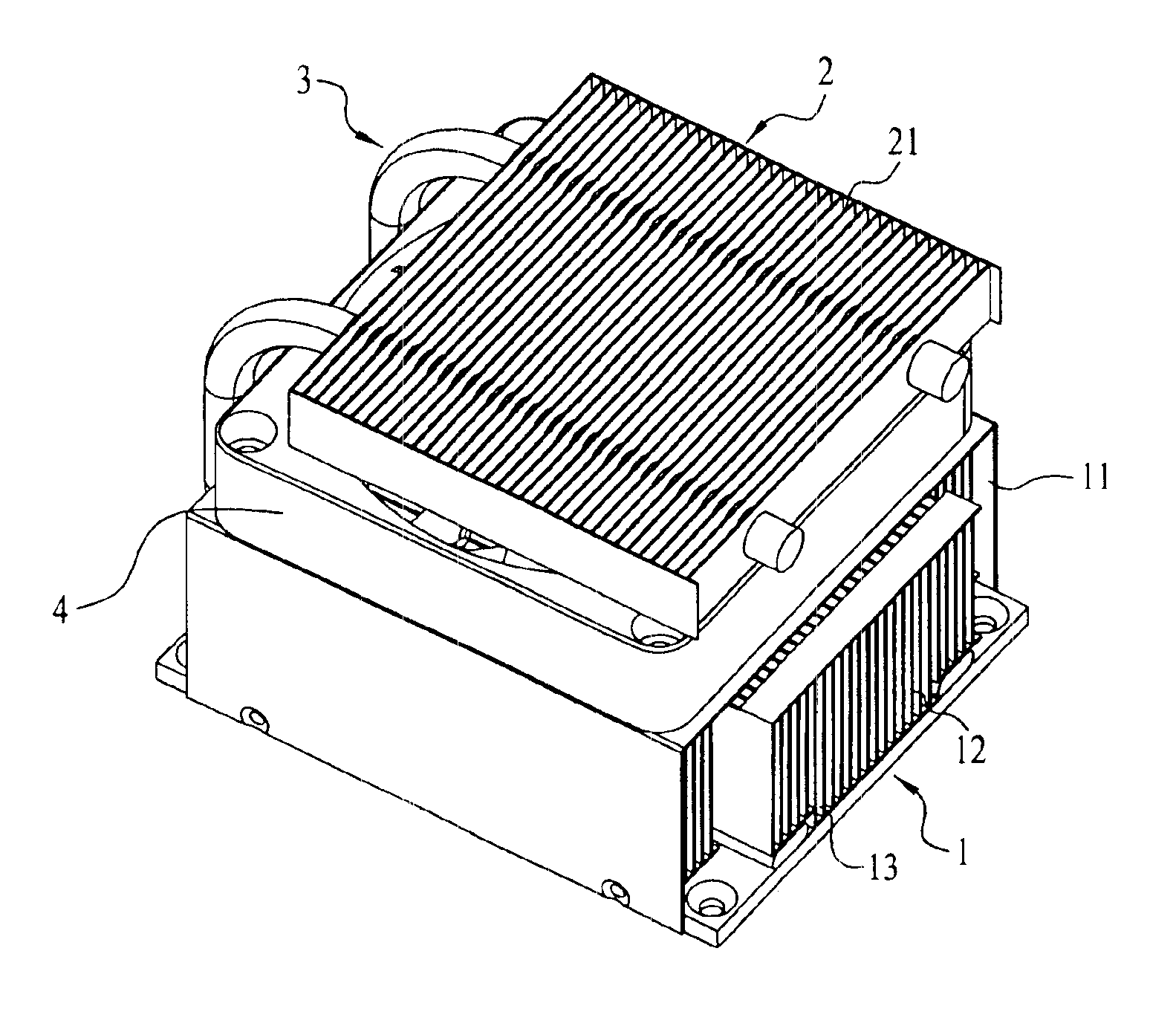
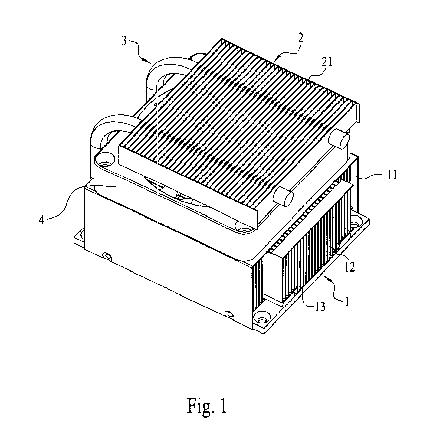
[0021]FIG. 1, FIG. 2 and FIG. 3 respectively are a view showing exterior of the present invention, a side view of the present invention and a top plan view of the present invention. As shown in the diagrams, the present invention provides a heat sink assembly with a heat pipe, composed of a first heat sink 1, a second heat sink 2 and a heat pipe 3. The first heat sink 1 and the second heat sink 2 become a main heat-dissipating region and a sub heat-dissipating region. Heat is dissipated first in the first heat sink 1 (the main heat-dissipating region) and then transferred via the heat pipe 3 to th second heat sink 2 (the sub heat-dissipating region) for being dissipated again.

[0022]A fan 4 is disposed on...


PUM


Abstract

The present invention provides a heat sink assembly. The heat sink assembly comprises a first heat sink with a fan disposed therein, a second heat sink and a heat pipe. The heat pipe has two ends respectively being disposed inside the first heat sink and the second heat sink, The heat pipe is disposed in a side of the first heat sink and the second heat sink and connects the first heat sink and the second heat sink with a space therein for positioning the fan. Therefore, the first heat sink and the second heat sink become a main heat-dissipating region and a sub heat-dissipating region. Heat is dissipated first in the first heat sink (the main heat-dissipating region) and then transferred via the heat pipe to the second heat sink (the sub heat-dissipating region) for being dissipated again.

Description

REFERENCE CITED[0001]1. Taiwan patent No.: 505379.[0002]2. Taiwan Patent No.: 504132.[0003]3. U.S. Pat. No.: 6,288,896.[0004]4. U.S. Pat. No.: 6,410,982.[0005]5. U.S. Pat. No.: 6,189,601.FIELD OF THE INVENTION[0006]The present invention is related to a heat sink assembly with a heat pipe. More particularly, the first heat sink and the second heat sink become a main heat-dissipating region and a sub heat-dissipating region. Heat is dissipated first in the first heat sink (the main heat-dissipating region) and then transferred via the heat pipe to the second heat sink (the sub heat-dissipating region) for being dissipated again.BACKGROUND OF THE INVENTION[0007]Generally speaking, conventional heat-dissipating apparatus is composed of a heat sink and a fan disposed in the heat sink for absorbing heat in central processing unit (CPU) and blowing or guiding air flow to dissipate heat. As the computer technology progresses, equipments and devices in personal computer field substantially v...

Claims


Application Information

Patent Timeline
IPC IPC(8): H01L23/467H01L23/427H01L23/34
CPCH01L23/427H01L23/467H01L2924/0002H01L2924/00
Inventor FAN, WEI-FENG
Owner DATECH TECH CO LTD
Why Eureka
Try Eureka