Fastener

a technology of fasteners and pins, which is applied in the field of fasteners, can solve the problems of large amount of force, difficult installation, and difficulty in insertion of parallel legs into small apertures, and achieve the effects of simple insertion of pins into apertures in items to be fastened, no force, and extra flexibility

Inactive Publication Date: 2005-06-28
NAT MOLDING
View PDF19 Cites 44 Cited by
  • Summary
  • Abstract
  • Description
  • Claims
  • Application Information

AI Technical Summary

Benefits of technology

[0015]Preferably, there are guide flanges located on an inner surface of the anchor arms, that guide the pin and keep it aligned with the central leg as it slides down toward the bottom of the anchor. The flanges extend out around one side of the anchor, on the opposite face of the pin from the channel, to prevent the pin from moving laterally beyond a predetermined limit. The pin has a notch cut into its lower end. When the bottom of the pin contacts the guide flange, the flange snaps into the notch and prevents upward movement of the pin. An additional notch and flange arrangement is located higher up on the pin and anchor assembly and also snaps closed to provide further insurance against upward movement of the pin after the fastener is in its fully locked position.
[0016]Preferably, the fastener can be set to a pre-loaded state prior to insertion into the items to be fastened. When the fastener is first molded, the pin is integrally formed with the anchor and extends up though an aperture in the top plate. The aperture is preferably U-shaped to accommodate the channel-containing pin structure. Pressing the push button down slightly causes the connections to the anchor to break and causes the pin to slide through the aperture into a partially inserted position. In this pre-loaded state, the fastener can be easily inserted into the items to be fastened, and then only a small pressing motion on the push pin can move the fastener into a fully locked position. Prior to achieving the fully locked position, the pin can freely move up and down within the anchor. There are preferably grooves on the pin that lock into protrusions located underneath the top plate after the pin has been fully inserted in the top plate, to prevent the pin from sliding back up out of the apertures after full insertion into the anchor.
[0017]The open V-shape of the anchor arms gives them extra flexibility so that insertion of the pin into apertures in the items to be fastened is simple and does not require a lot of force. Similarly, pressing the push pin into the anchor legs does not require a lot of force for the legs to extend outward and lock the fastener to the items to be fastened.
[0018]Because the fastener is molded with the pin and anchor already together, it does not require any assembly to use. Traditional two-piece anchor systems require assembling of the pin and anchor prior to use, requiring additional time and causing additional operator fatigue. In the present invention, all that is required to use the anchor is depressing the pin enough to break the connections and pre-load the fastener. This can be done on the manufacturing end or on the assembly line.

Problems solved by technology

While this type of fastener is widely used, the closed V-shape of the anchor makes it difficult to install.
These fasteners all suffer the same drawback as Beglinger: the closed V formation of the anchor is so resistant to bending that a large amount of force is required to insert the fastener, and bring it into a locked position.
This fastener suffers the drawback that the parallel legs are more difficult to insert into a small aperture in the item, as they must often be squeezed together by the operator's fingers in order for the anchor to be inserted.

Method used


Image

  • Fastener
  • Fastener
  • Fastener

Examples


Embodiment Construction

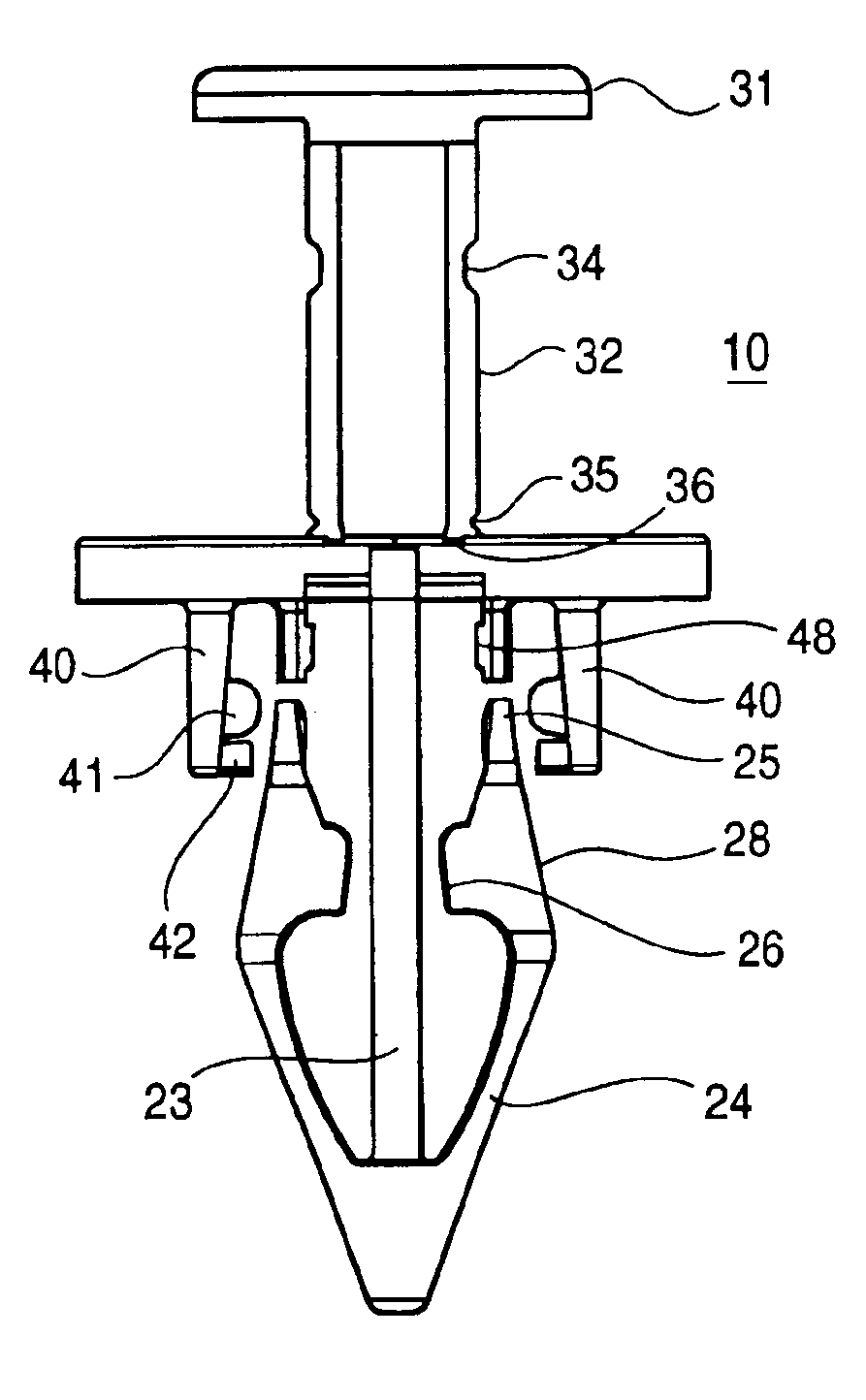
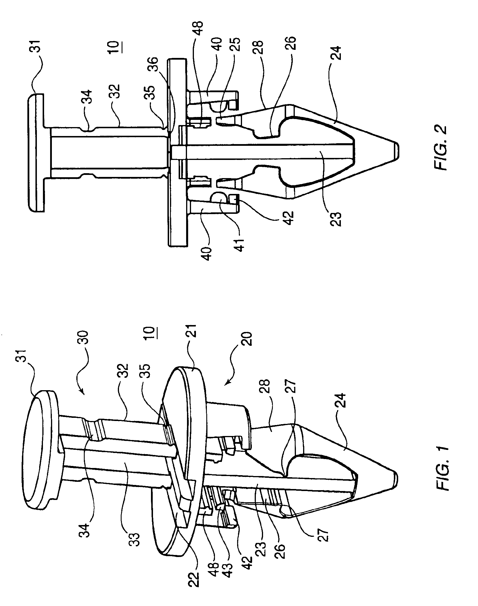
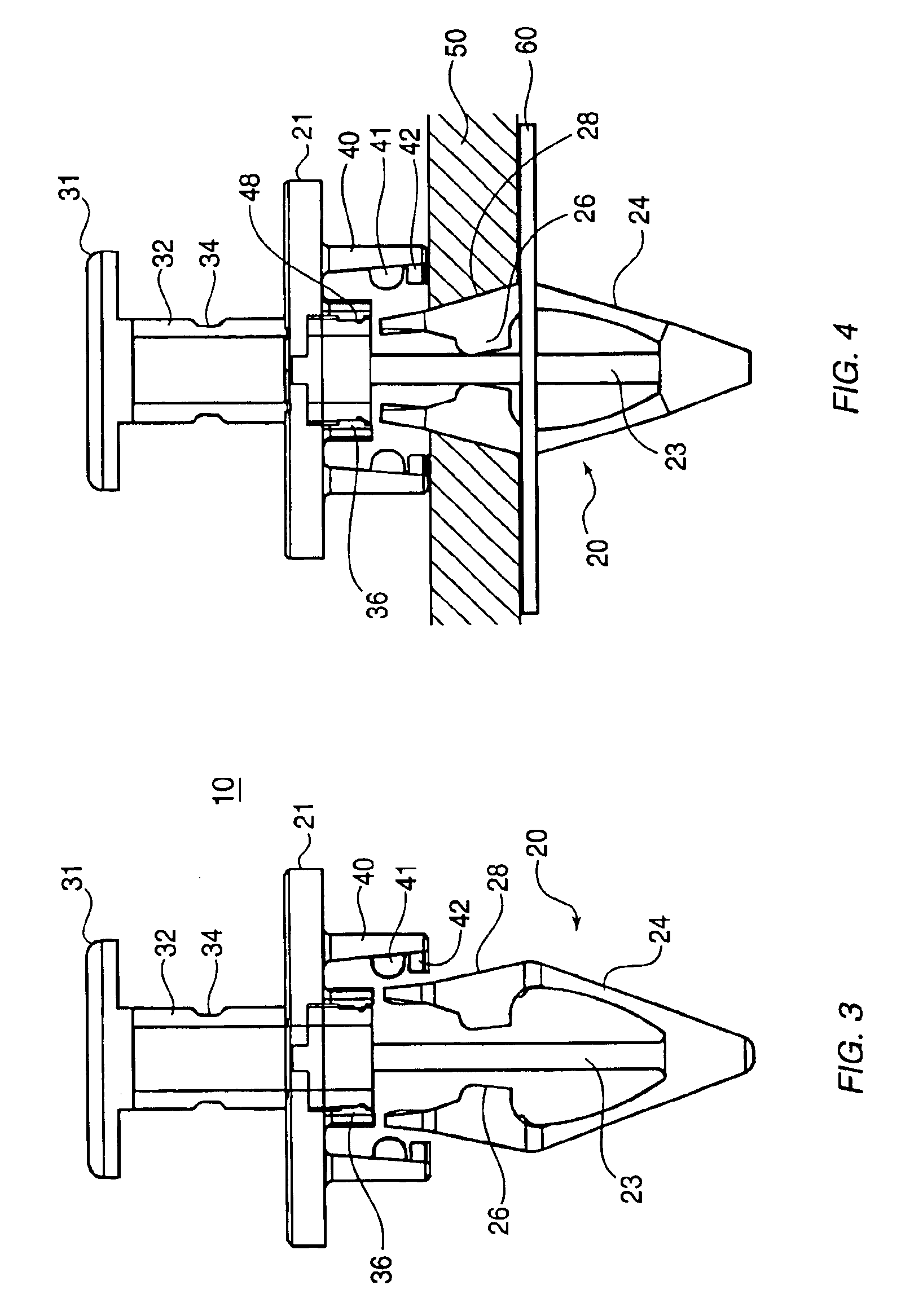
[0029]Referring now in detail to the drawings, FIGS. 1-6 show the fastener 10 according to the invention as it goes from an initially molded state (FIG. 1) into a fully locked position (FIG. 6) FIGS. 1 and 2 show the fastener 10 according to the invention in an initial molded state. Fastener 10 comprises an anchor 20 and a push pin assembly 30. Anchor 20 has a top plate 21 connected to a central leg 23. Central leg 23 extends substantially perpendicular to the bottom surface of top plate 21. There are two flexible anchor arms 24 connected to the free end of central leg 23. Each anchor arm 24 extends up and away from central leg 23, and each anchor arm 24 has a free end 25 that is not connected to anything. Anchor arm 24 has a tapered top portion 28 that widens as arm 24 extends from its free end 25 back toward the tip of central leg 23, creating a slanted wall facing central leg 23.

[0030]Push pin assembly 30 comprises a push button 31 and a pin 32 connected to and extending downward...


PUM


Abstract

A fastener comprises an anchor and a central pin. The anchor has a top plate to which a central leg is connected. At the free end of the central leg are two anchor arms that extend up and outward from the free end, forming an arrowhead shape. The anchor arms are flexible and can flex inward as the anchor is placed through a hole in an item to be fastened. Connected to the top surface of the top plate is a push pin. Depressing the push pin breaks the connection areas to create a two-piece anchor from the single part. The push pin comprises a push button and a pin connected to the underside of the push button. The pin consists of a vertical post having a channel therein for accommodating the central leg of the anchor. Pushing the push button downward causes the anchor arms to be pushed outward and to anchor the fastener into the items to be fastened.

Description

BACKGROUND OF THE INVENTION[0001]1. Field of the Invention[0002]This invention relates to a fastener for fastening two planar objects together. In particular, the invention relates to a fastener comprising an anchor and a push pin that is particularly useful for fastening automotive body panels to sheet metal.[0003]2. The Prior Art[0004]Anchor type fasteners having a central pin are known. For example, U.S. Pat. No. 4,571,134 to Seglinger et al. shows a two-piece plastic fastener comprising an anchor and a central pin. The anchor comprises a closed V-shaped insertion portion and a top plate. The anchor is placed through two (or more) planar items to be fastened together. A central pin extends down between the arms of the V and causes the arms to spread when the pin is fully depressed. This spreading anchors the fastener in the rear item and prevents the fastener from coming out. The plate prevents the front item from coming away from the rear item. While this type of fastener is wid...

Claims


Application Information

Patent Timeline
Patent Type & Authority Patents(United States)
IPC IPC(8): F16B19/04F16B19/10
CPCF16B19/1081Y10T24/309
Inventor ANSCHER, JOSEPH
Owner NAT MOLDING
Why Eureka
Try Eureka