Engine with fuel injection system

a fuel injection system and engine technology, applied in the direction of engines, fuel injection with sensors, liquid fuel feeders, etc., can solve the problems of high damage to the fuel pressure sensor, and increase the stress at the bosses, so as to achieve high stress, increase the stress, and the effect of high pressur

Inactive Publication Date: 2005-07-05
YAMAHA MARINE KK
View PDF28 Cites 12 Cited by
  • Summary
  • Abstract
  • Description
  • Claims
  • Application Information

AI Technical Summary

Benefits of technology

[0013]Additionally, the fuel rail does not heat up as much as the engine because fuel flowing through the fuel rail tends to cool the fuel rail. The fuel rail, therefore, does not expand as much as the engine portions, if it expands at all. The difference in the expansion rates between the engine and the fuel rail can cause high stress at the bosses. In addition, the relatively high pressure of the fuel flowing through the fuel rail and the engine vibrations can increase the stress at the bosses. A two-cycle engine needs higher pressure than a four-cycle engine, because the duration of injection for the two-cycle engine running in a relatively high-speed range is shorter than that for the four-cycle engine. The higher pressure in the two-cycle engine further increases the stress at the bosses.
[0014]Features of the present invention improve the fuel pressure sensor and fuel rail mounting structures. In particular, aspects of the present invention provide improved sensor mounting structures that can inhibit engine vibrations from being transmitted to the fuel pressure sensor. Additionally, aspects of the present invention can improve fuel rail mounting structures.

Problems solved by technology

Accordingly, the engine vibrations can damage the fuel pressure sensor.
The difference in the expansion rates between the engine and the fuel rail can cause high stress at the bosses.
In addition, the relatively high pressure of the fuel flowing through the fuel rail and the engine vibrations can increase the stress at the bosses.
The higher pressure in the two-cycle engine further increases the stress at the bosses.

Method used


Image

  • Engine with fuel injection system
  • Engine with fuel injection system
  • Engine with fuel injection system

Examples


Embodiment Construction

Overall Construction of Outboard Motor

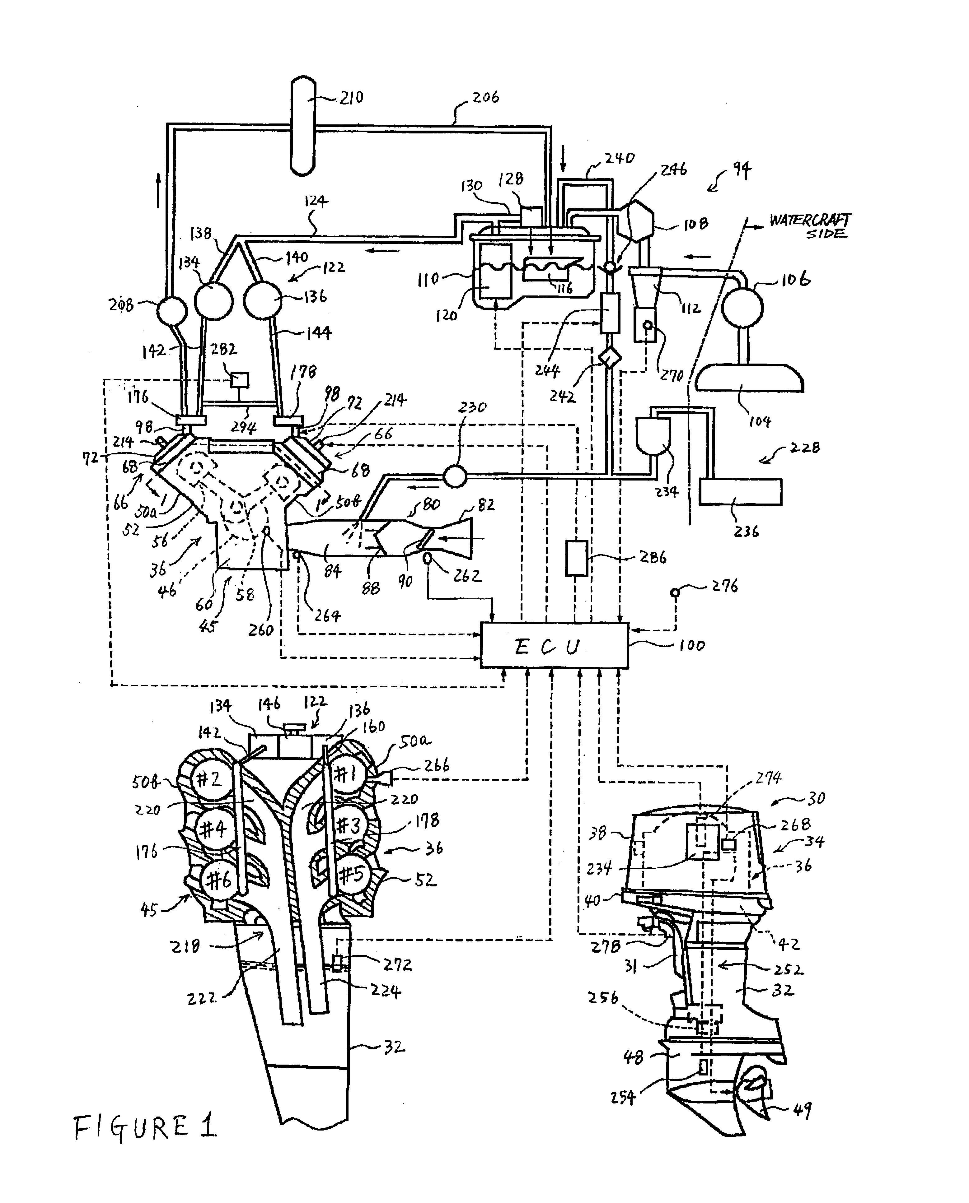
[0046]With reference to FIGS. 1-8, one possible environment in which the present invention can be practiced is described below. The present fuel supply system has particular utility in the context of a marine engine, and thus, the system is described in the context of an outboard motor. The fuel supply system, however, can be used with other types of internal combustion engines. For example, the fuel supply system can be used with any machines using engine power such as watercrafts, land vehicles and utility machines.

[0047]With initial reference to FIG. 1, and in particular to the lower-right hand view of FIG. 1, an outboard motor 30 is depicted from the side. The outboard motor 30 has a bracket assembly 31 comprising a swivel bracket and a clamping bracket, which are typically associated with a driveshaft housing 32. The bracket assembly 31 is similar to that of another outboard motor shown in FIG. 15 and will be described with reference to FIG...


PUM


Abstract

An engine incorporates a fuel injector to supply fuel to a combustion chamber defined in an engine body. At least one fuel rail defines a fuel passage through which fuel is supplied to the fuel injector. The fuel rail is mounted to the engine body. A fuel pump pressurizes the fuel. A sensor unit is elastically mounted to the fuel rail. The sensor unit has a fuel pressure sensor that detects a pressure of the fuel pressurized by the fuel pump. The engine body has bosses that project therefrom. The engine body defines bolt holes that extend through the bosses and into the engine body adjacent to the bosses. A threaded section is formed in each bolt hole in the engine body adjacent to the corresponding boss. A bolt is screwed down into each threaded section. A portion of each bolt is spaced apart from an inner surface of a corresponding bolt hole to reduce the effects of thermal expansion of the engine body and the fuel rail.

Description

PRIORITY INFORMATION[0001]This application is based on and claims priority to Japanese Patent Applications Nos. 2002-117200 (filed on Apr. 19, 2002) and 2002-149597 (filed on May 23, 2002), the entire contents of which are hereby expressly incorporated by reference.BACKGROUND OF THE INVENTION[0002]1. Field of the Invention[0003]The present invention generally relates to a fuel injection engine, and more particularly relates to a fuel injection engine that incorporates a fuel conduit through which fuel is supplied to the engine.[0004]2. Description of Related Art[0005]In all fields of engine design, there is an emphasis on obtaining more effective emission control, achieving better fuel economy and increasing power output. This trend has led to the use of fuel injection systems, as opposed to carburetors, as the engine charge former.[0006]Some fuel injection systems inject fuel into the air intake manifold. Direct fuel injection systems inject fuel directly into the combustion chambe...

Claims


Application Information

Patent Timeline
Patent Type & Authority Patents(United States)
IPC IPC(8): F02M63/02F02M55/02F02B75/00F02M63/00F02B75/22F02B61/04F02B61/00F02B1/08F02B75/18F02B75/12F02B1/00
CPCF02B61/045F02B75/22F02M55/025F02M63/0225F02B1/08F02B2075/125F02B2075/1824F02M2200/24Y02T10/123Y02T10/12
Inventor KATO, MASAHIKO
Owner YAMAHA MARINE KK
Why Eureka
Try Eureka