Electrohydraulic control unit

Inactive Publication Date: 2005-07-05
NAT OILWELL VARCO LP
View PDF10 Cites 20 Cited by
  • Summary
  • Abstract
  • Description
  • Claims
  • Application Information

AI Technical Summary

Benefits of technology

[0010]The present invention disclosed herein comprises an electrohydraulic control unit for operating the hydraulic actuators of surface safety valves and subsurface safety valves. Each control unit includes a closed loop reservoir of hydraulic fluid that minimizes the volume of hydraulic fluid necessary to operate the actuators and eliminates the need for a remotely located hydraulic control panel by utilizing a low voltage computer operated electrical system for operating the control units. The control units may be attached to existing surface safety valve actuators and subsurface safety actuators thereby minimizing the cost of operating the system of the present invention.

Problems solved by technology

It has been found, however, that the use of pneumatic controlled actuators for surface safety valves is limited due to the size requirements of the actuator piston needed to operate gate valves particularly for high pressure and high volume flow lines which may require large bore gate valves.
In addition, due to condensation and contamination within the air system utilized for pneumatic actuation, it has been found that venting of the air into the atmosphere is environmentally unsatisfactory.
It has been found, however, that the gate and actuator piston in a hydraulic system will stroke at a limited speed due to the flow rate of hydraulic fluid and the volume of hydraulic fluid that is typically used in hydraulic systems.
It has been found, however, that as with hydraulic actuated surface safety valves, the volume of hydraulic fluid in the hydraulic system affects the speed and depth at which the subsurface safety valves will operate.

Method used


Image

  • Electrohydraulic control unit
  • Electrohydraulic control unit
  • Electrohydraulic control unit

Examples


Embodiment Construction

[0022]While the making and using of various embodiments of the present invention is discussed in detail below, it should be appreciated that the present invention provides many applicable inventive concepts which can be embodied in a wide variety of specific contexts. The specific embodiments discussed herein are merely illustrative of specific ways to make and use the invention, and do not delimit the scope of the invention.

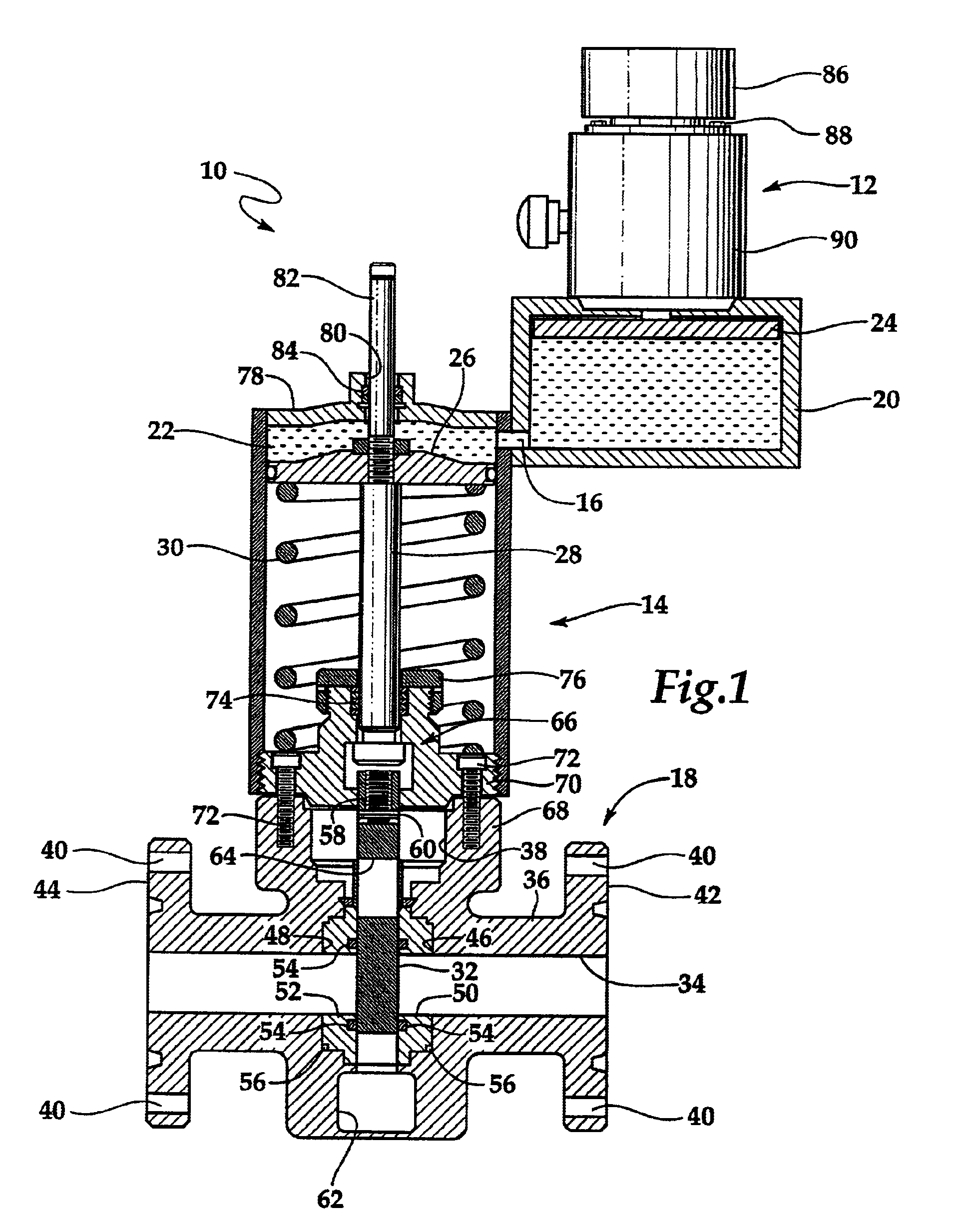
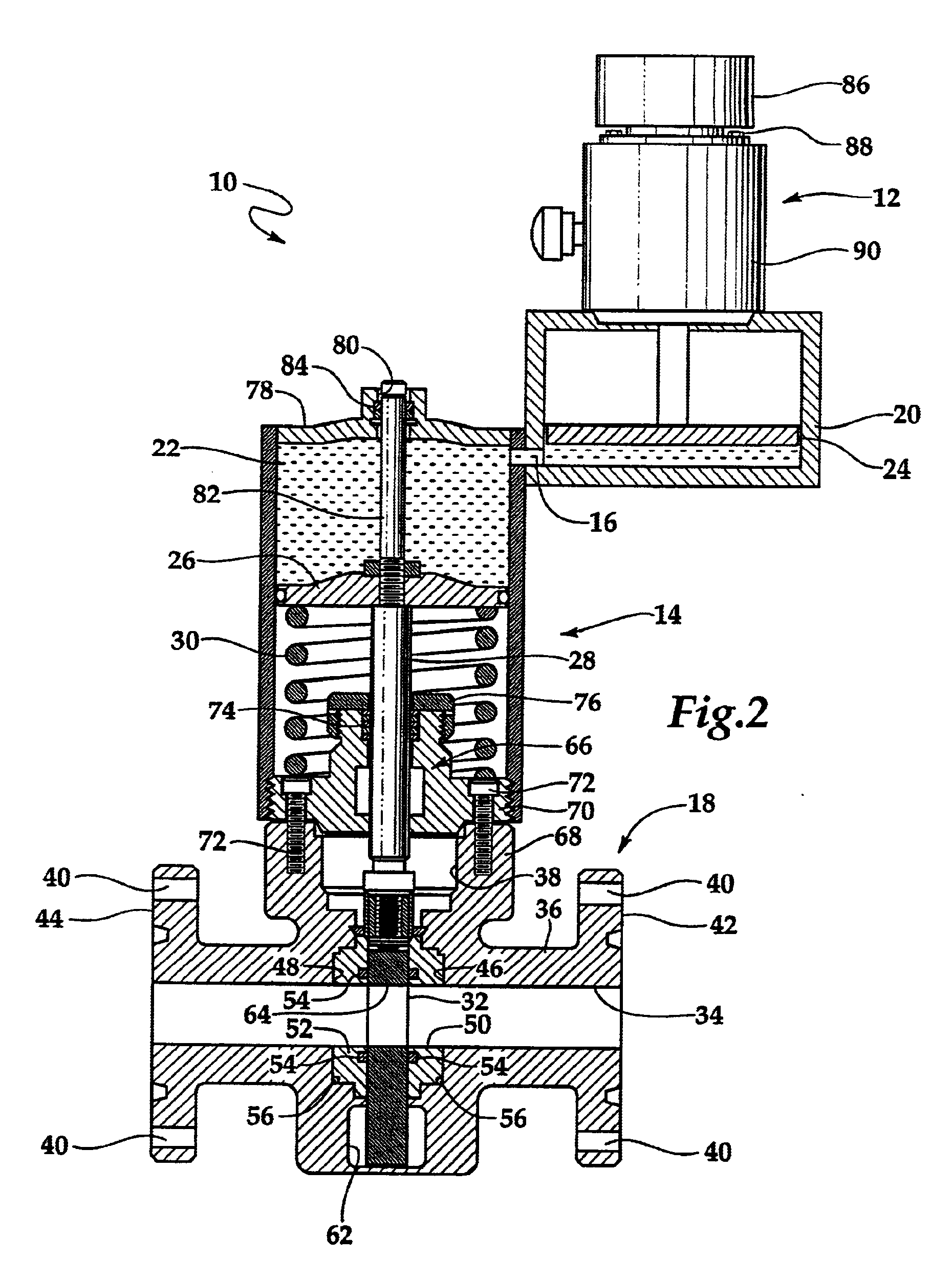
[0023]Referring now to FIG. 1, an electrohydraulic control unit coupled to a hydraulic actuator of a surface safety valve is depicted in generally designated 10. Electrohydraulic control unit 12 is coupled to hydraulic actuator 14 via hydraulic coupling 16. Hydraulic actuator 14 is assembled onto surface safety valve 18 which is designed for controlling the flow of fluids through a flow line from a source, such as a well head, to a remote processing or storage location. Surface safety valve 18 is adapted for connection into the flow line adjacent to the well for...


PUM


Abstract

An electrohydraulic control unit for operating an actuator of a hydraulically controllable device is disclosed. The electrohydraulic control unit comprises a housing including a chamber for hydraulic fluid. The housing is coupled to the actuator such that a path for fluid communication between the chamber and the actuator is created. Disposed within the chamber is a piston for regulating the flow of the hydraulic fluid between the chamber and the actuator. An electric motor is securably attached to the housing. The electric motor includes a selectively rotatable shaft. The electrohydraulic control unit also comprises a converter configured to transform the rotational motion of the shaft to translational motion of the piston, thereby controlling the actuation of the hydraulically controllable device.

Description

[0001]This application is a division of application Ser. No. 09 / 089,921 filed on Jun. 3, 1998, now U.S. Pat. No. 6,102,828.TECHNICAL FIELD OF THE INVENTION[0002]This invention relates, in general, to safety systems for the production of oil and gas, and in particular to, an electrohydraulic control unit for operating the hydraulic actuator of, for example, surface safety valves and subsurface safety valves.BACKGROUND OF THE INVENTION[0003]Formation fluids, including oil and gas produced at a well head are typically conveyed through flow lines to remote processing equipment. It is conventional practice to use surface safety valves which are responsive to changes in operating conditions to automatically shut off flow in the flow lines at the onset of unusual or unscheduled operating conditions. Such surface safety valve installations are designed to automatically close in response to fluctuations in selected conditions in the flow lines, either above or below predetermined settings, s...

Claims


Application Information

Patent Timeline
IPC IPC(8): E21B34/00E21B34/02E21B34/16E21B33/03E21B33/035
CPCE21B33/0355E21B34/02E21B34/16F16K31/124
Inventor MACKENZIE, ROY
Owner NAT OILWELL VARCO LP
Why Eureka
Try Eureka