Anti-panic mechanism of vehicle door latch device

a technology of anti-panic mechanism and vehicle door latch, which is applied in the directions of door locks, applications, transportation and packaging, etc., can solve the problems of inability to reduce the frequency of panic state, and achieve the effect of reducing the frequency of occurrence of panic sta

Inactive Publication Date: 2005-07-05
MITSUI KINZOKU ACT
View PDF7 Cites 20 Cited by
  • Summary
  • Abstract
  • Description
  • Claims
  • Application Information

AI Technical Summary

Benefits of technology

[0010]It is an object of the present invention to provide an improved anti-panic mechanism of a v

Problems solved by technology

Therefore, even after the unlocking operation was performed by the switch of the central door lock and the like, the panic state occurs when the outside door handle is manipulated before the lock lever crosses over the dead point by the motor power.
Since such a timing of the panic state occurrence is common to the

Method used


Image

  • Anti-panic mechanism of vehicle door latch device
  • Anti-panic mechanism of vehicle door latch device
  • Anti-panic mechanism of vehicle door latch device

Examples


Embodiment Construction

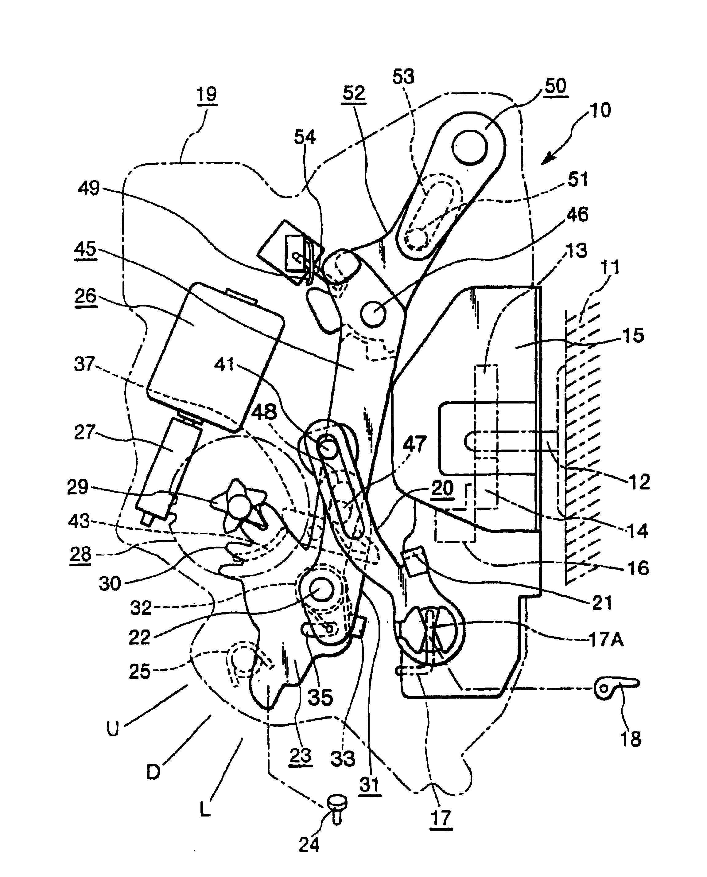
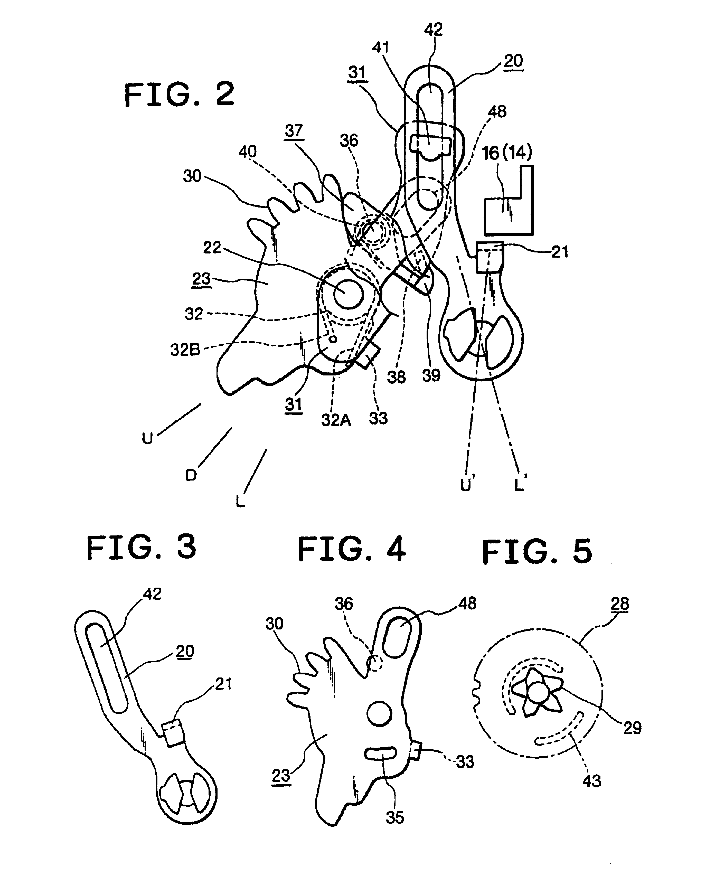
[0023]FIG. 1 shows an interior side view of a door latch device according to the present invention. The door latch device is constituted by a latch assembly 10 to be mounted on a door (not shown) and a striker 12 to be fixed to a vehicle body 11. The latch assembly 10 has a latch 13 engageable with the striker 12 when the door is closed, and a ratchet 14 engageable with the latch 13 so as to hold an engagement with the latch 13 and the striker 12. The latch 13 and the ratchet 14 are pivotally mounted on the front side of a latch body 15 by shafts (not shown) extending in a back-and-forth direction of the latch body 15. The ratchet 14 has a pin 16 which is engageable with an abutting portion 21 of an open link 20. In FIG. 1, when the ratchet pin 16 moves upward, the latch 13 is released from ratchet 14, thereby the door is opened.

[0024]An open lever 17 is pivotally mounted on the rear side of the latch body 15 by shaft (not shown) extending in the front-and-back direction of the latc...


PUM


Abstract

An anti-panic mechanism comprises a lock lever displaceable between an unlocked position and a locked position, an over center spring urging the lock lever to either side of the unlocked position and locked position with a dead point, an open link displaceable between an engaging position and a non-engaging position, an output member displacing the lock lever by a motor, an anti-panic spring urging the open link toward the engaging position from the non-engaging position, a connecting lever connecting the open link to the lock lever. The connecting lever releases the open link before the lock lever crosses over the dead point of the over center spring when the output member is rotated in the unlocking direction.

Description

BACKGROUND OF THE INVENTION[0001]1. Field of the Invention[0002]The present invention relates to an anti-panic mechanism of a vehicle door latch device.[0003]2. Description of the Related Art[0004]In the conventional prevailing vehicle door latch devices, unlocking operations by an inside lock button, a remote control transmitter and the like are not normally completed if the outside open handle of a door is in the state of being manipulated by an opening operation, nor is it possible to open the door. Such a state is referred to as a panic state in the industry. When plunged into the panic state, the outside open handle is restored to a non-operation state and, then, the unlocking operation is performed again by the central door lock system and the like and, after that, the opening operation of the door handle is performed again, so that the door is opened. That is, two unlocking operations and two door opening operations are required until the door is opened. Thus, in the present ...

Claims


Application Information

Patent Timeline
IPC IPC(8): E05B65/12E05B65/20B60J5/00E05B85/24E05B77/32E05B79/08
CPCE05B81/06E05B81/16E05B81/34E05B77/32Y10T292/1047Y10T292/1082
Inventor INOUE, JIRO
Owner MITSUI KINZOKU ACT
Why Eureka
Try Eureka