

Electrical outlet box with alternative mounting flanges
a technology of mounting flanges and outlet boxes, which is applied in the installation of lighting conductors, electrical apparatus casings/cabinets/drawers, coupling device connections, etc., can solve the problems of cumbersome existing arrangements for providing such alternative mounting of the same box, and achieve the effect of not affecting use and convenient us
- Summary
- Abstract
- Description
- Claims
- Application Information
AI Technical Summary
Benefits of technology
Problems solved by technology
Method used
Image

Examples
Embodiment Construction
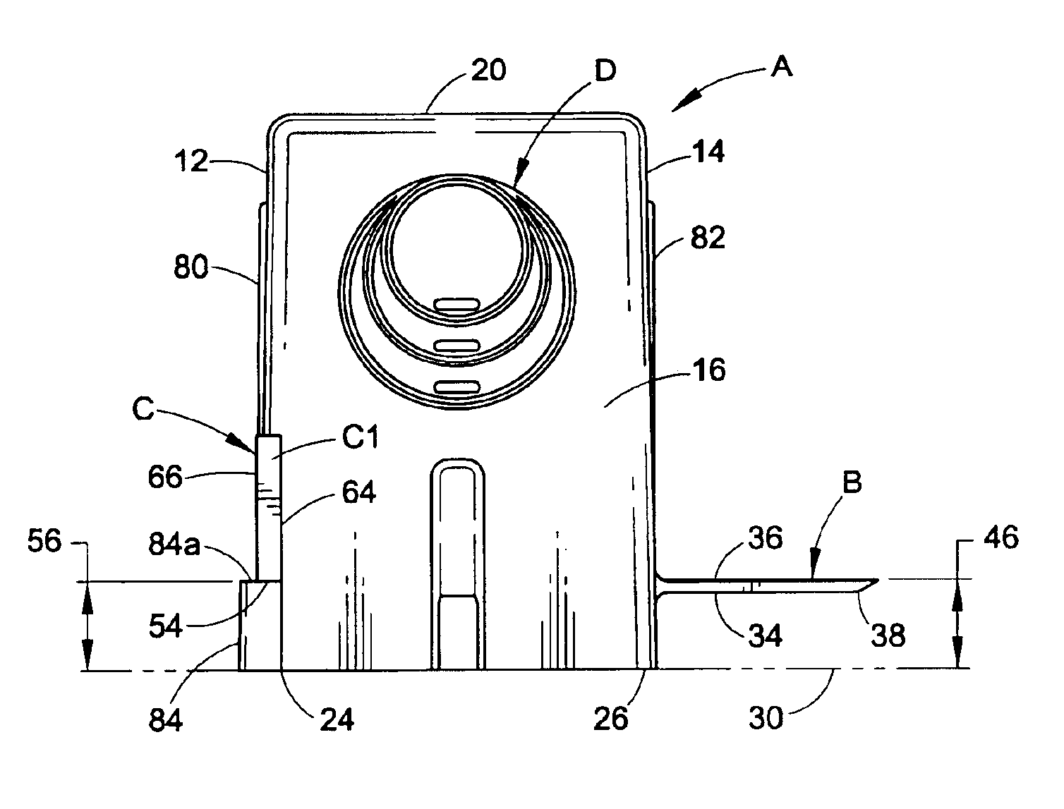
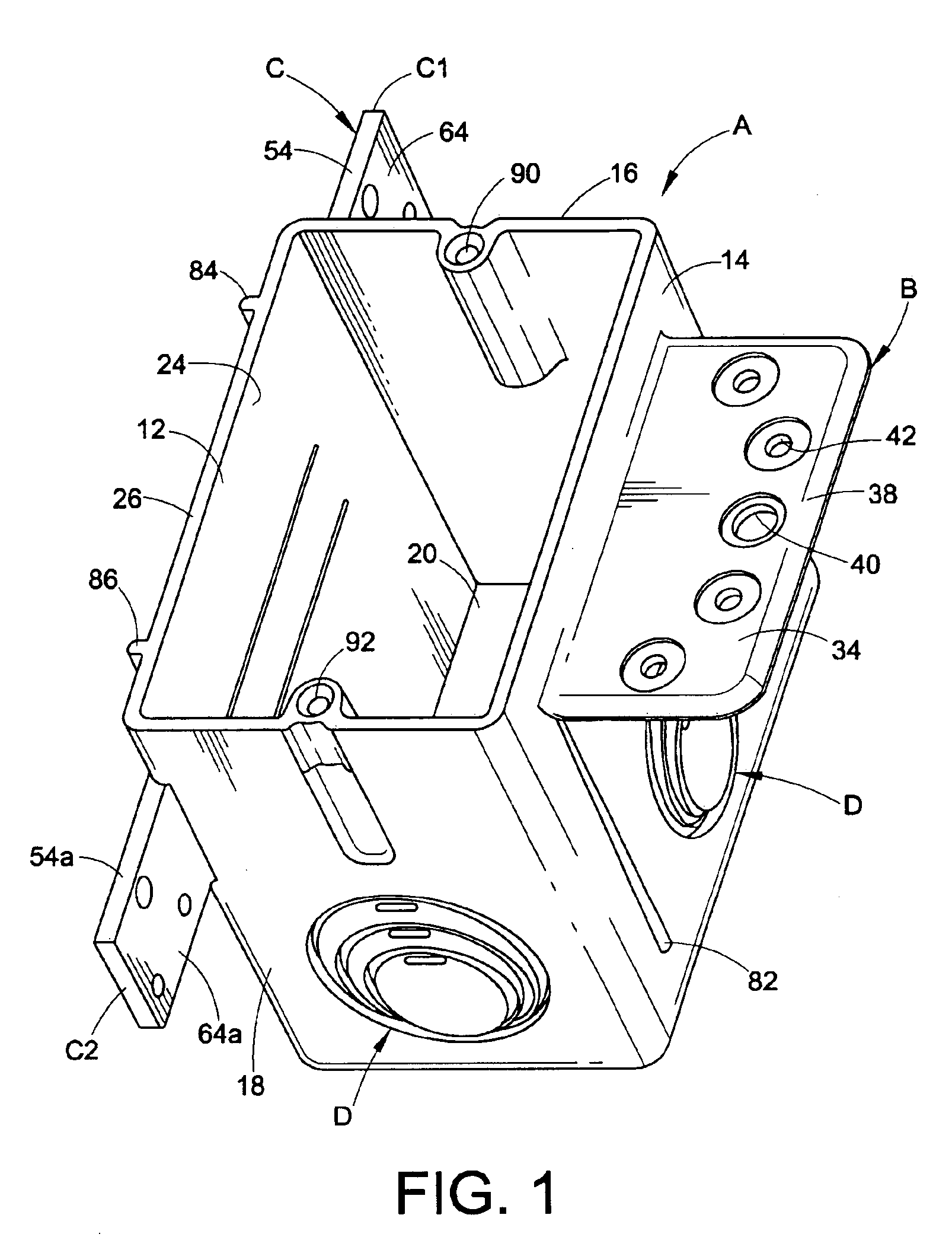
[0016]Referring now to the drawing, wherein the showings are for purposes of illustrating a preferred embodiment of the invention only and not for purposes of limiting same, FIG. 1 shows an electrical outlet box A molded in one-piece of plastic material such as, but not necessarily limited to, polycarbonate or polyvinylcholoride, the latter also being known as PVC. Although a single gang outlet box is illustrated in the drawings, it will be appreciated that the improved mounting arrangement of the present application applies equally to two-gang outlet boxes as well as to electrical boxes of other types.
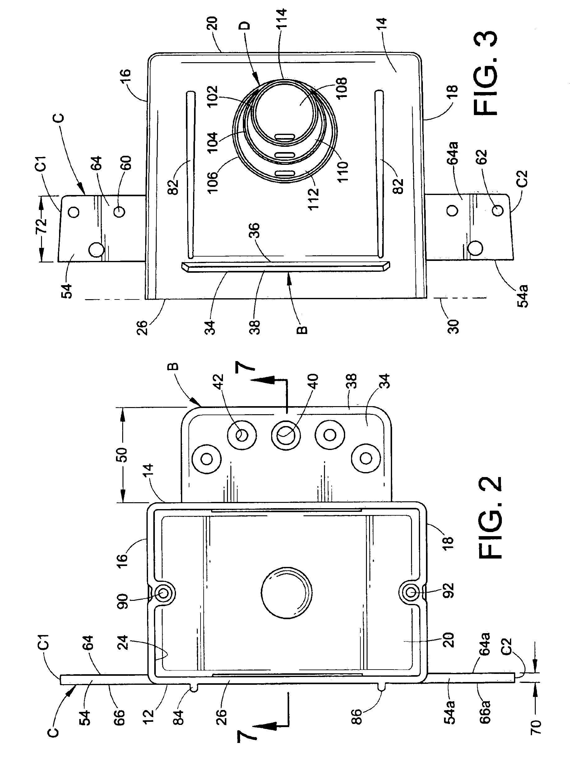
[0017]Box A has opposite sidewalls 12 and 14, top and bottom walls 16 and 18, and a rear wall 20. A rectangular front opening 24 opposite from bottom wall 20 is surrounded by a box front surface 26 that lies in a plane that is represented by shadow line 30 in FIGS. 3, 4 and 6. Box A may be rotated 180° so that top wall 16 becomes the bottom wall and bottom wall 18 becomes the top wall...
PUM
 Abstract
Description
Claims
Application Information