

Semi-transmissive liquid crystal display device
a liquid crystal display and semi-transmissive technology, applied in the field of semi-transmissive liquid crystal display devices, can solve the problems of significant difficulty in designing the structure of the device and processing the signal, and the inability to optimize the intensity of light exiting the device, so as to achieve the effect of improving the viewing angle characteristics
- Summary
- Abstract
- Description
- Claims
- Application Information
AI Technical Summary
Benefits of technology
Problems solved by technology
Method used
Image

Examples
first embodiment
(First Embodiment)
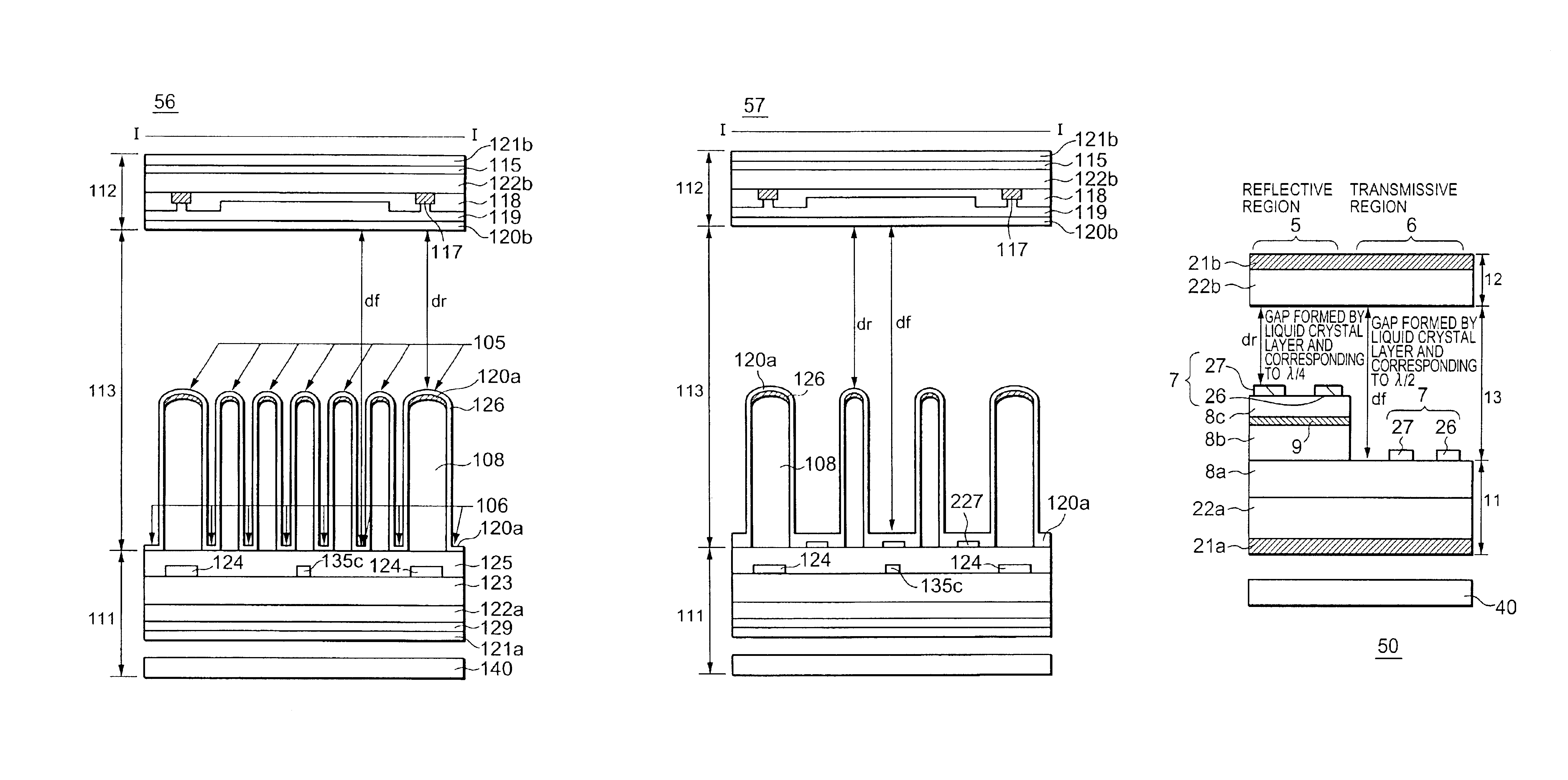
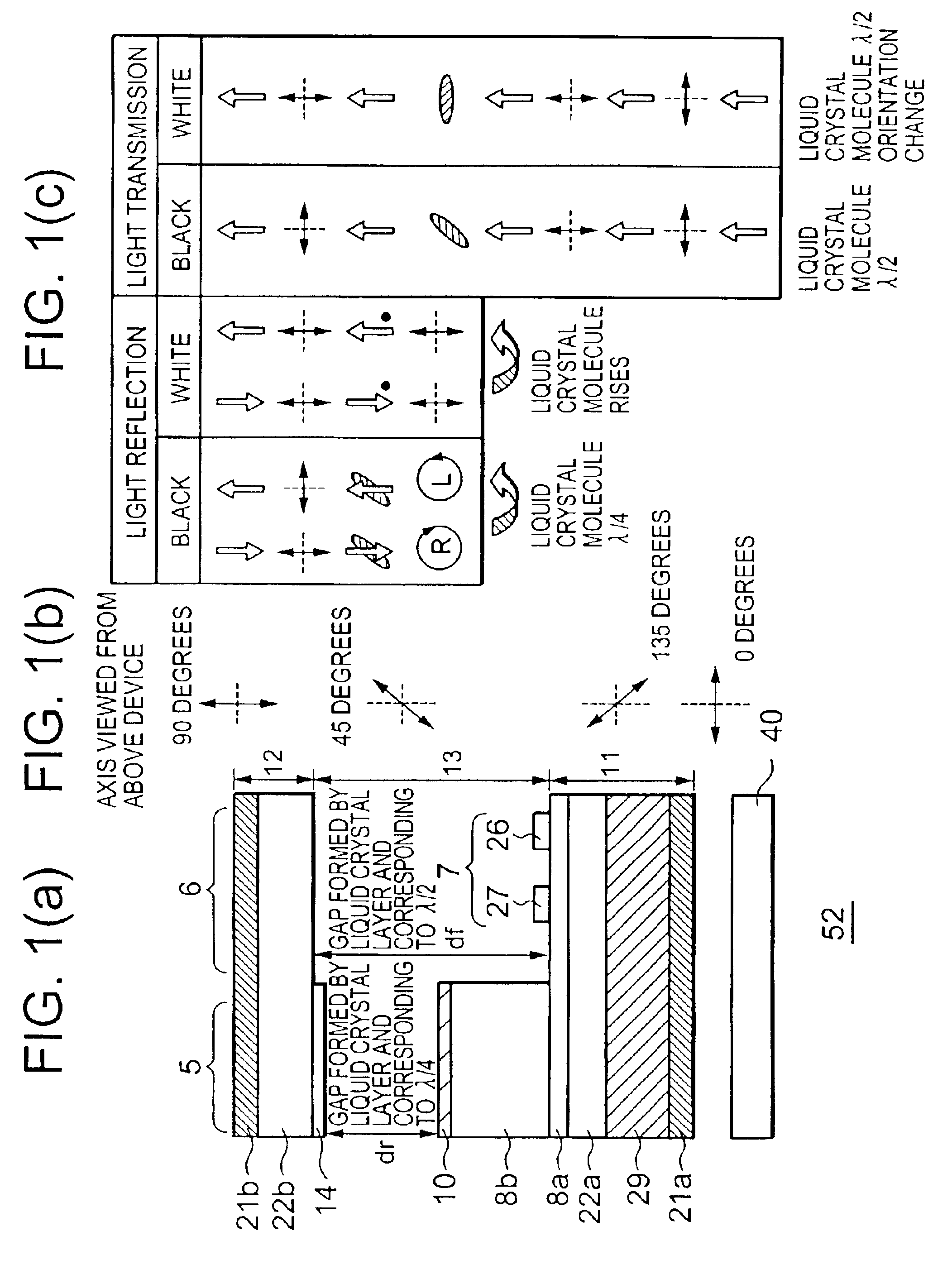
[0076]A semi-transmissive liquid crystal display device of a first embodiment of the invention has a reflective region, in which liquid crystal molecules are driven by a vertical electric field, and a transmissive region, in which liquid crystal molecules are driven by a horizontal electric field. FIG. 1(a) is a cross sectional view illustrating how components constituting a cell of a semi-transmissive liquid crystal display device 52 of the first embodiment are optically arranged and FIG. 1(b) illustrates an alignment angle at which polarizers 21a, 21b, a liquid crystal layer 13 and a one-half wavelength (λ / 2) plate 29 are oriented relative to one another when viewing the device from the side of an opposing substrate 12, and FIG. 1(c) illustrates how those components operate in the reflective and transmissive regions.
[0077]As shown in FIG. 1(a), the semi-transmissive liquid crystal display device 52 includes: a lower substrate 11; an opposing substrate 12; a liqui...
second embodiment
(Second Embodiment)
[0083]A semi-transmissive liquid crystal display device of a second embodiment of the invention has liquid crystal molecules driven by a horizontal electric field in both a reflective region and a transmissive region. FIG. 4(a) is a cross sectional view illustrating how a cell of a semi-transmissive liquid crystal display device 53 of the second embodiment is optically arranged and FIG. 4(b) illustrates an alignment angle at which polarizers 21a, 21b, a liquid crystal layer 13 and a one-half wavelength plate 29 are oriented relative to one another when viewing the device from the side of an opposing substrate 12, and FIG. 4(c) illustrates how those components operate in the reflective and transmissive regions.
[0084]As shown in FIG. 4(a), since the semi-transmissive liquid crystal display device 53 of the second embodiment has the same cross sectional configuration as that shown in FIG. 20(a) except that the device 53 has the one-half wavelength plate 29, the expla...
third embodiment
(Third Embodiment)
[0087]Although in the first and second embodiments, only how the liquid crystal display device is configured to have the components optically arranged and operates has been explained, in a third embodiment, how layer structure and electrode configuration employed in the second embodiment are built will be explained with reference to FIGS. 5 through 10. FIG. 5 is a plan view of a liquid crystal display device 54 of the third embodiment and FIG. 6 is a plan view of an interconnect level in which an electrode 7 provided in the transmissive region and provided for generation of horizontal electric field is formed, and FIG. 7 is a plan view of an interconnect level in which an electrode 7 provided in the reflective region and provided for generation of horizontal electric field is formed. FIG. 8(a) is a cross sectional view taken along line I—I of FIG. 5 and FIG. 8(b) is a cross sectional view taken along line IV—IV of FIG. 5. FIG. 9(a) is a cross sectional view taken a...
PUM
 Abstract
Description
Claims
Application Information