
Apparatus for driving fasteners, including screws, nails, pop riverts and staples

a technology for fasteners and accessories, applied in the direction of screwdrivers, wrenches, spanners, etc., can solve the problems of reducing the ease of operation of screwdrivers, tools are needed to adjust the stop base, and are not always at hand, so as to achieve convenient mounting and centered on the tool.

Inactive Publication Date: 2005-07-12
C & E FEIN
View PDF12 Cites 42 Cited by
  • Summary
  • Abstract
  • Description
  • Claims
  • Application Information

AI Technical Summary

Benefits of technology

[0006]One disadvantage of the latter configuration is that a tool is needed for adjusting the stop base, namely for loosening and then retightening the screws. Said tool may be lost and is not always at hand when an adjustment has to be made. This diminishes the ease of operation of the screwdriving tool.
[0035]This enables the equipment of the invention to be mounted easily and centeredly onto the tool. This method of attachment is also advantageous because the drive motors made by a given manufacturer often have cylindrical surfaces with the same dimensions, thus enabling a form of attachment that can be used universally for different models.

Problems solved by technology

One disadvantage of the latter configuration is that a tool is needed for adjusting the stop base, namely for loosening and then retightening the screws.
Said tool may be lost and is not always at hand when an adjustment has to be made.
This diminishes the ease of operation of the screwdriving tool.

Method used


Image

  • Apparatus for driving fasteners, including screws, nails, pop riverts and staples
  • Apparatus for driving fasteners, including screws, nails, pop riverts and staples
  • Apparatus for driving fasteners, including screws, nails, pop riverts and staples

Examples


first embodiment

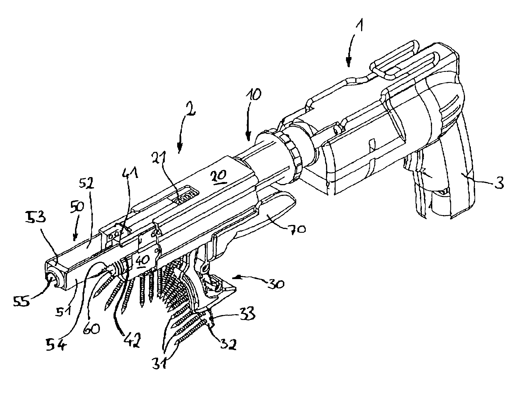
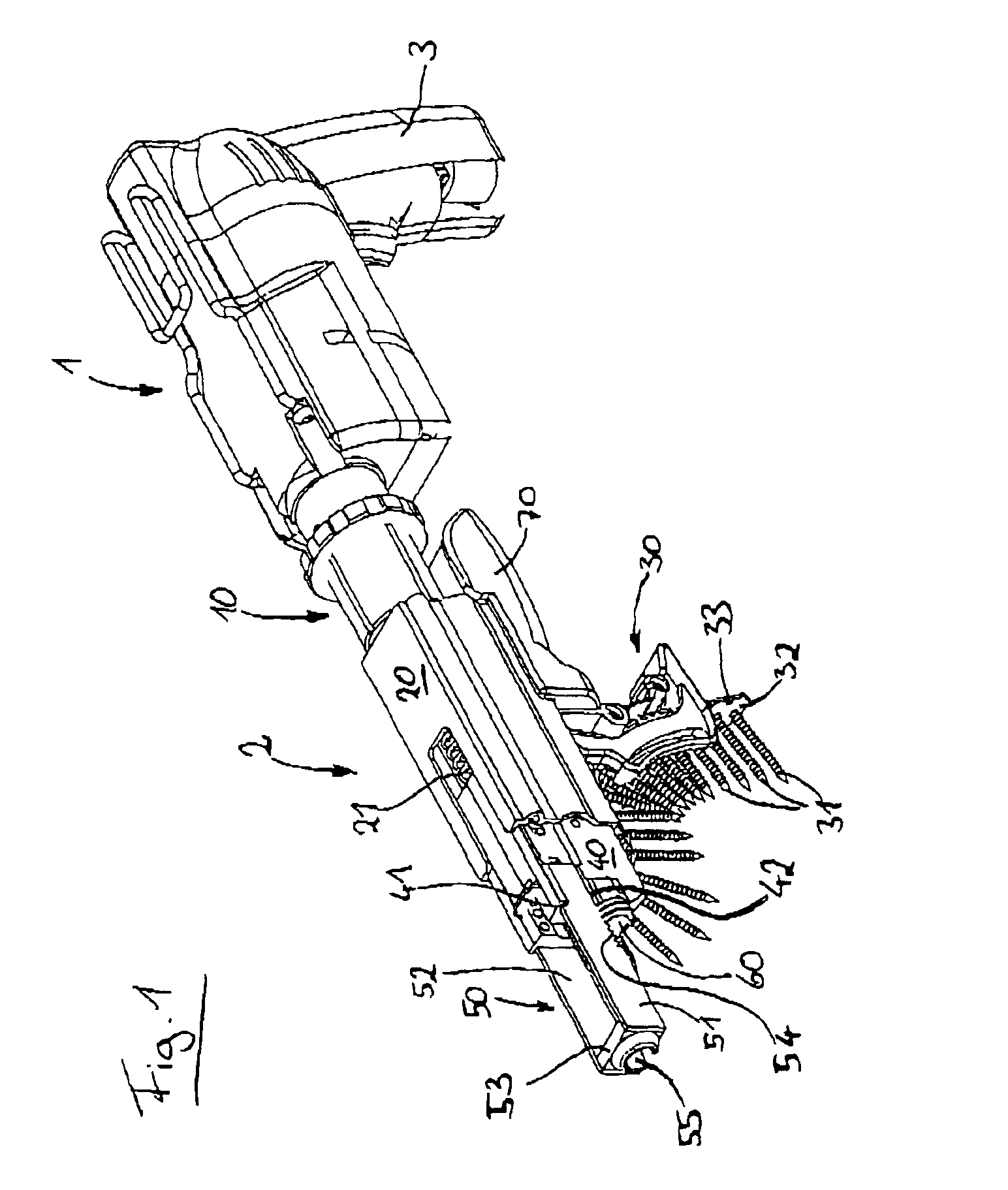
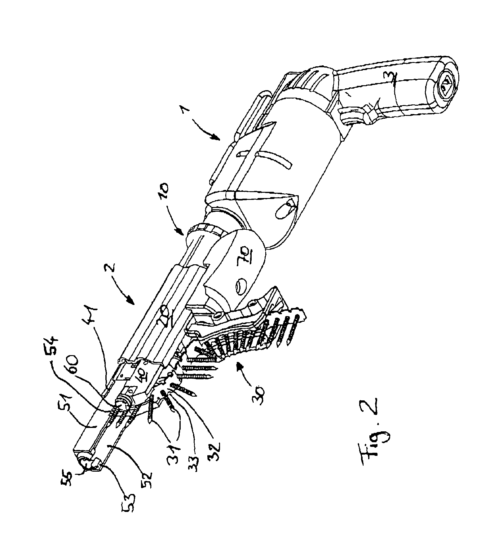
[0060]As can be seen from FIGS. 1-10, an equipment according to the invention comprises an electrically powered drive motor 1 and a feeder 2 flange-mounted to said drive motor. The feeder 2 is connected to drive motor 1 by means of a flange-clamped connector 10 positioned concentric to the rotational axis of the drive shaft of the drive motor. The flange-clamped connector 10 fixes a first housing portion 20 of the feeder device 2 to the housing of drive motor 1 in a stationary position.

[0061]On the lower side of feeder device 2 there is disposed a magazine 30 into which a plurality of screws 31 connected at their screw heads by a magazine belt 32 can be fed. Screws 31 may also be referred to as fasteners. Inside the first housing portion 20, a second housing portion 40 is disposed that is displaceable relative to the first housing portion 20. The second housing portion 40 can move relative to the first housing portion 20 in the direction of the rotational axis of drive motor 1. A pr...

second embodiment

[0072]In the equipment according to the invention as shown in FIGS. 11-17, a threaded worm 60a is rotatably mounted in a stationary position inside the second housing portion 40 in such a way that its rotational axis is concentric with the rotational axis of the screwdriver bit. As can be seen from FIG. 13 in particular, threaded worm 60a has a central bore 61 through which the screwdriver bit or a coupling device receiving the screwdriver bit is able to extend in order to transmit torque from drive motor 1 into screws 31. At the outer encasing surface of threaded worm 60a, and in the same manner as in threaded worm 60, a trapezoidal thread 62 is defined that engages with a plurality of parallel ridges in stop member shanks 51, 52. Ridges 57 and slots 56 between ridges 57 extend perpendicular to the rotational axis of threaded worm 60a. When threaded worm 60a is turned, a force is transferred via ridges 57 from threaded worm 60a to the stop member 50, causing a displacement of the s...


PUM

PropertyMeasurementUnit
Forceaaaaaaaaaa
Widthaaaaaaaaaa

Abstract

Apparatus for driving fasteners, in particular screws, nails, pop rivets, and staples, is disclosed. It has a motor-drivable feeder that moves the fasteners sequentially from a feed position into a driving position, and with an adjustor has a manually rotatable threader mounted stationary on the feeder. The thread engages interlockingly with the stop member.

Description

BACKGROUND OF THE INVENTION[0001]The invention relates to equipment for driving fasteners, in particular screws, nails, pop rivets, staples or the like, with a motor-drivable feeder.[0002]Such equipment is known and is used in various configurations for driving fasteners into workpieces, and in particular for driving a plurality of fasteners in rapid succession. With such equipment, it is not necessary to remove the fasteners manually from a bulk pack, attach them to the workpiece and apply the matching tool to the fastener; instead, the fasteners are automatically fed by the drivable feeder to the location where they are to be driven into the workpiece, and the fasteners are guided in such a manner that the driving tool automatically engages with the fastener that has been fed to it.[0003]It is preferred in industry and the craft trades to use tools with feeders of the aforementioned kind when it is necessary to drive a plurality of fasteners into a workpiece in rapid succession an...

Claims


Application Information

Patent Timeline
IPC IPC(8): B25B23/04B25B23/00B25B23/02B21J15/00B21J15/34
CPCB21J15/32B21J15/323B25B23/0064B25B23/045
Inventor KIGEL, ALEXANDERREISS, VOLKER
Owner C & E FEIN
Learn More