Liquid container, cap used with the liquid container, and cap-equipped liquid container

a technology for liquid containers and liquid containers, which is applied in printing and other directions, can solve the problems of ink scattering, latch levers being detached from the ink tank body, and material used to be vulnerable to repeated bending, and achieve the effect of easy removal

Inactive Publication Date: 2005-07-12
CANON KK
View PDF17 Cites 33 Cited by
  • Summary
  • Abstract
  • Description
  • Claims
  • Application Information

AI Technical Summary

Benefits of technology

[0017]With the cap of the present invention, the cap is fitted to the liquid container by engaging the first and second latch members respectively with the first and second engagement members provided on the opposing side walls of the liquid container. The elastic sealing member for sealing off the surroundings of the supply port of the liquid container is provided on the bottom wall portion connecting the first and second latch members to each other, and therefore the supply port is protected by the bottom wall portion. Also, since the tab used in the operation of removing the cap is provided near the first latch member to lie in the direction of extension of the bottom wall portion, the first latch member is first disengaged and the second latch member is then disengaged. In this connection, since a part of the bottom wall portion is able to elastically deform upon application of the operating force for removing the cap from the liquid container, a shock occurred upon opening the supply port of the liquid container is reduced and the cap can be easily removed without troubles.

Problems solved by technology

This tendency leads to a result that a material vulnerable to repeated bending is employed as the material of an ink tank body in some cases depending on the kinds of inks used.
In trying to fabricate the ink tank, which as disclosed in the above-cited Japanese Patent Laid-Open No. 8-58107, etc. has a latch lever, using such a material, a risk has been found in that when the ink tank is handled in an unexpected way far from the normal one, e.g., when the user puts a finger between the ink tank body and the latch lever and applies a force to the finger in a direction of moving the latch lever away from the ink tank body, the latch lever may be detached from the ink tank body.
On the other hand, the following problem has been experienced with the cap of the ink tank.
Therefore, particularly when the ink tank has a small size, there is a risk that, depending on how the ink tank is held by the user, the ink may scatter through the ink supply port, or one or both of the ink tank and the cap may slip off and drop from the user's hand.

Method used


Image

  • Liquid container, cap used with the liquid container, and cap-equipped liquid container
  • Liquid container, cap used with the liquid container, and cap-equipped liquid container
  • Liquid container, cap used with the liquid container, and cap-equipped liquid container

Examples


Embodiment Construction

[0038]The present invention will be described below in detail with reference to the drawings.

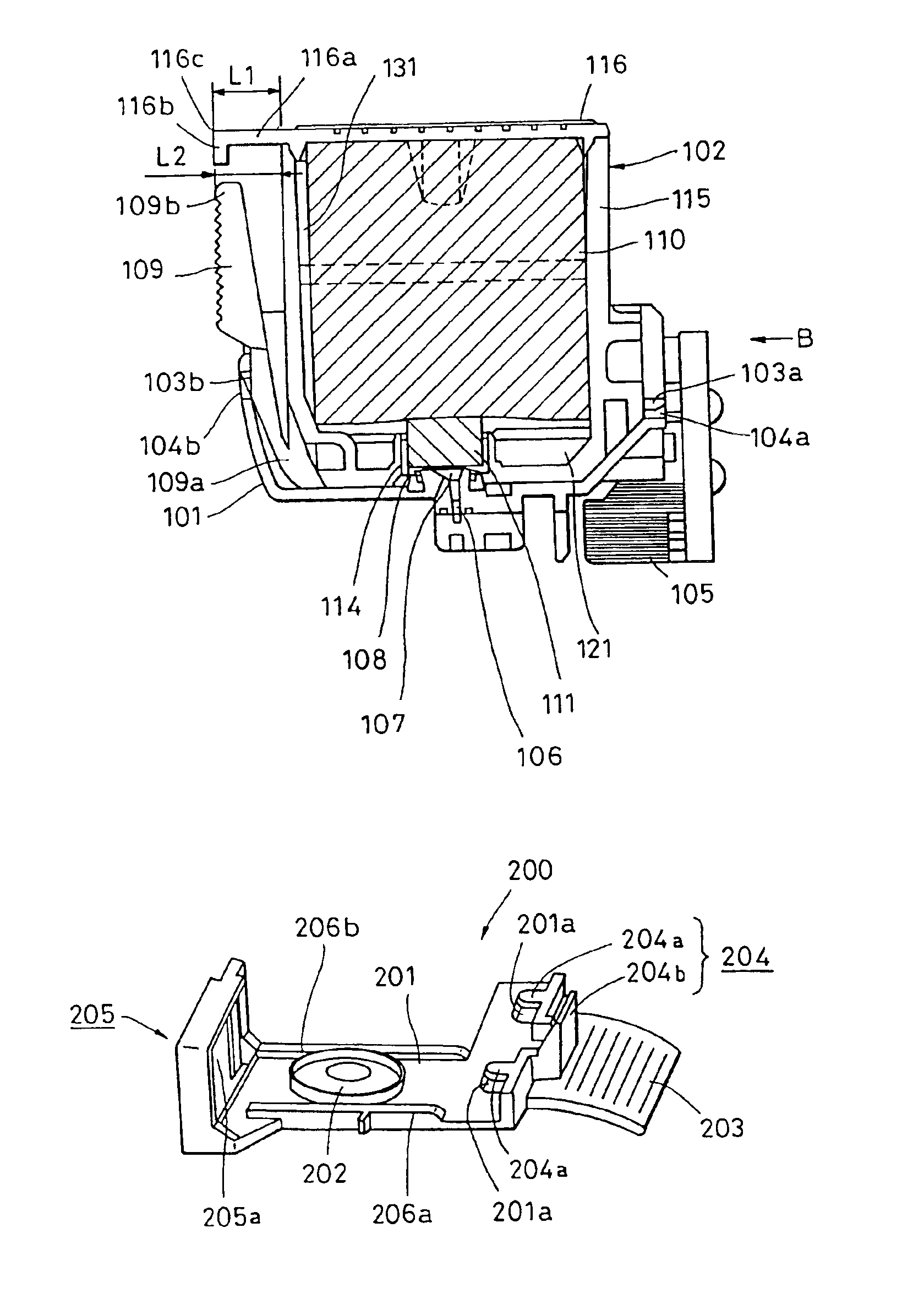
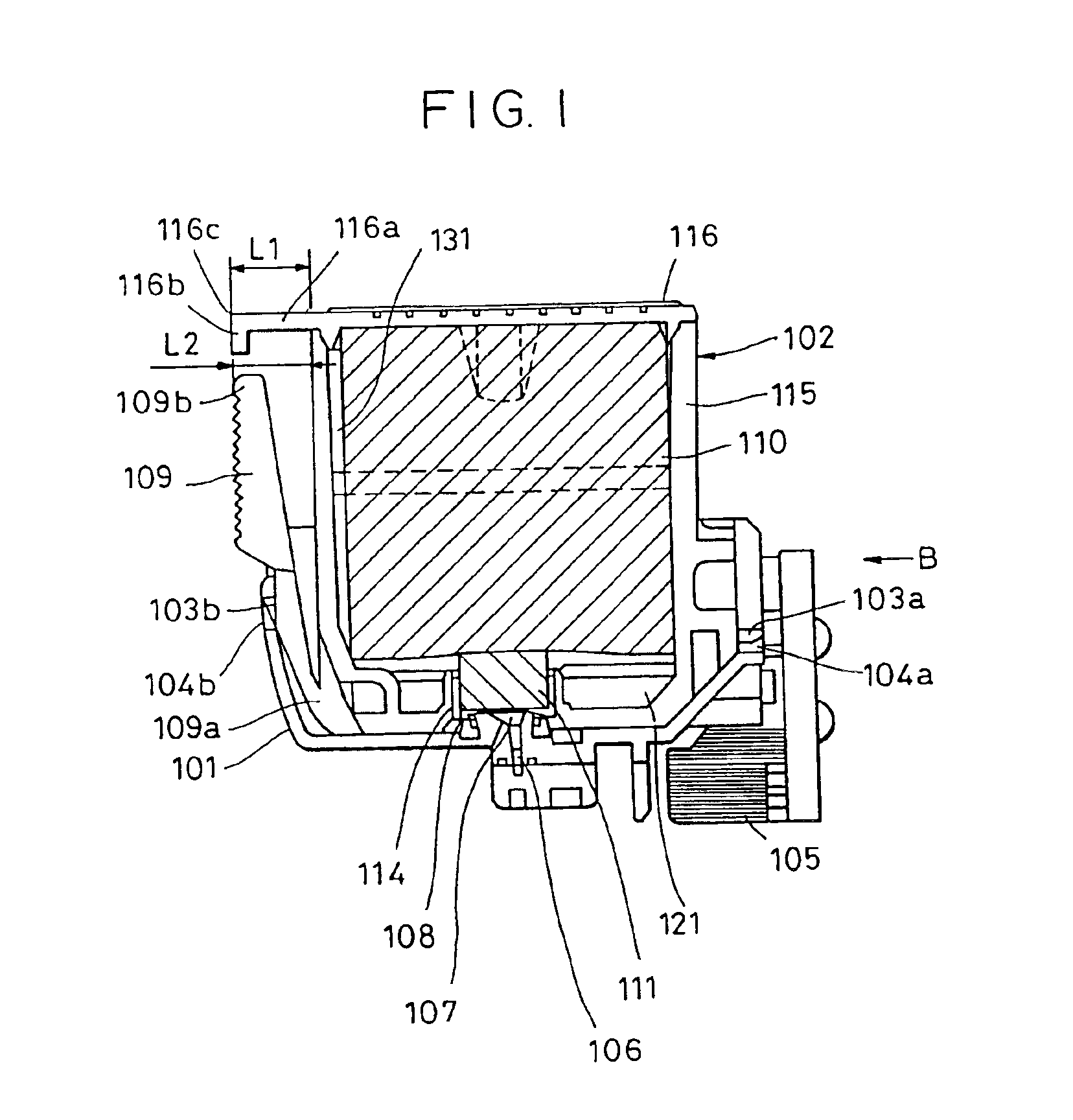
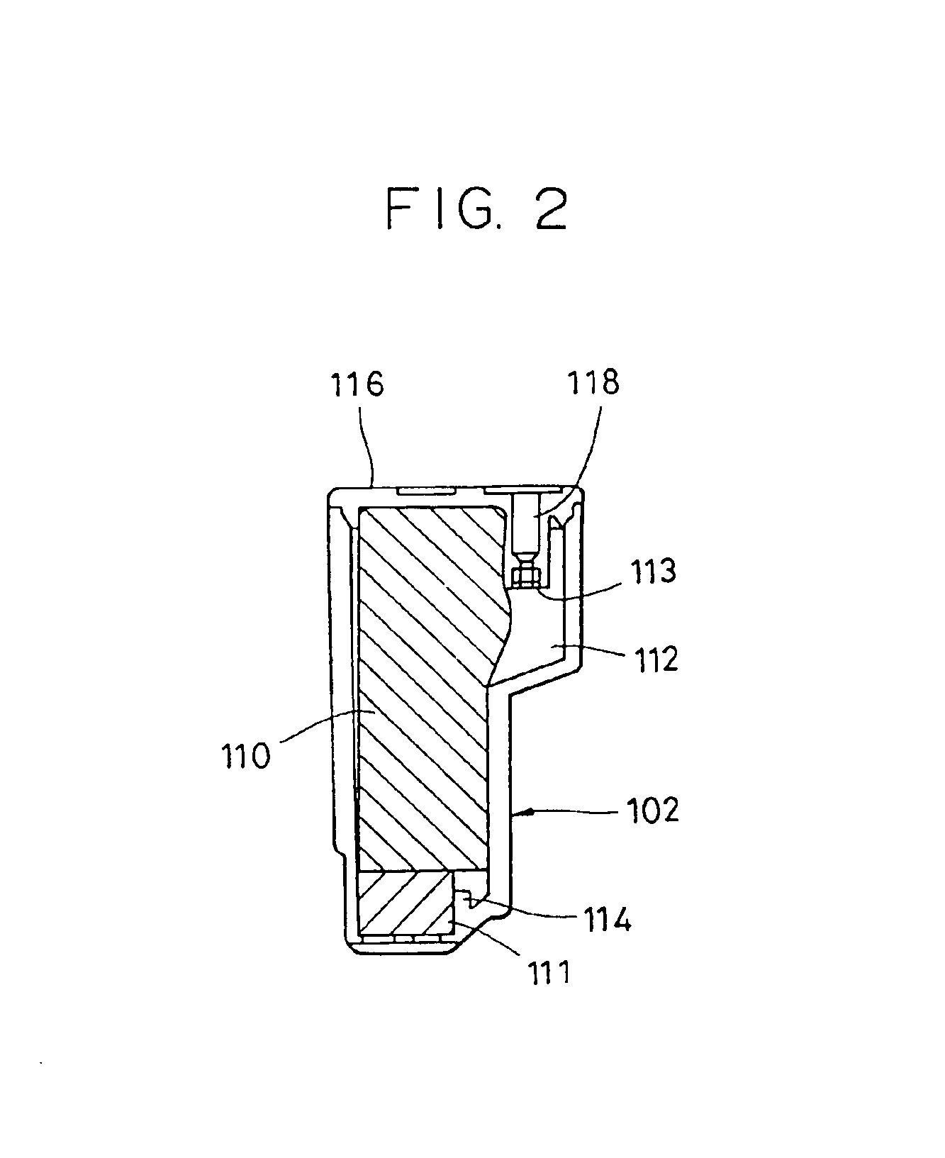
[0039]First, an overall construction of the ink tank of the present invention will be described with reference to FIG. 1. FIG. 1 is a sectional view showing the structure of the ink tank according to one embodiment of the present invention, and FIG. 2 is a side sectional view showing the structure of the ink tank shown in FIG. 1, as viewed in the direction of arrow B.

[0040]As shown in FIG. 1, an ink tank 102 is provided with a first engagement member (latch claw) 103b and a second engagement member 103a for fixing the ink tank 102 to an ink tank holder 101 including a recording head 105. The ink tank 102 is fixedly attached to the ink tank holder 101 by fitting the second engagement member 103a to an opening 104a formed in the ink tank holder 101 as a second catch member for catching the second engagement member 103a to be locked in place, and by fitting the first engagement member 103b to a...


PUM


Abstract

A liquid container includes a lever having one end supported to an outer wall of a housing containing a liquid therein and the other end as a free end, the lever being elastically deformable. The liquid container further includes a projection provided in an area of the housing which is opposite to and away from the supported one end of the lever, the projection covering at least a part of a space between the free end of the lever and the housing in the above area. By virtue of the projection, the lever can be protected against accidental external forces. In a cap-equipped liquid container, a straight line connecting a projected end of the projection of the liquid container and a distal end of a tab of a cap is set to cross a movable range of the lever provided on the liquid container in which the lever is allowed to angularly move with elastic deformation thereof. In a cap, an elastic sealing member for sealing off the surroundings of the supply port of the liquid container is provided on a bottom wall portion connecting first and second latch members to each other, and a part of the bottom wall portion is able to elastically deform upon application of an operating force.

Description

[0001]This application is a division of U.S. application Ser. No. 09 / 678,024, filed Oct. 4, 2000, now U.S. Pat. No. 6,623,104.BACKGROUND OF THE INVENTION[0002]1. Field of the Invention[0003]The present invention relates to a liquid container and a cap for sealing off a supply port of the liquid container. More particularly, the present invention relates to an ink tank for use with an ink jet recording head in which an ink is ejected for recording, and a cap for sealing off an ink supply port of the ink tank.[0004]2. Description of the Related Art[0005]There is known a combination of a liquid ejection recording head (ink jet recording head) in which a liquid (taking an ink as an example in the following description) is ejected for recording, and a liquid container (ink tank) for containing the ink supplied to the recording head. From the viewpoint of operating cost, the combination has been hitherto often practiced such that the ink tank is attached to the recording head in a detacha...

Claims


Application Information

Patent Timeline
Patent Type & Authority Patents(United States)
IPC IPC(8): B41J2/175
CPCB41J2/17513B41J2/1752B41J2/17536B41J2/17553
Inventor KOTAKI, YASUOABE, TSUTOMUNAKAYAMA, SHIGEYUKIOGAWA, MASASHI
Owner CANON KK
Why Eureka
Try Eureka