Utility vehicles

a technology for utility vehicles and spreaders, applied in the field of utility vehicles, can solve the problems of increasing the difficulty, time and effort of changing equipment, and removing the spreader bed in addition to the spreader, so as to improve the efficiency and efficiency of utility vehicles

Inactive Publication Date: 2005-07-12
DEERE & CO
View PDF36 Cites 51 Cited by
  • Summary
  • Abstract
  • Description
  • Claims
  • Application Information

AI Technical Summary

Benefits of technology

[0015]Another advantage of the present invention is to provide multi-purpose platforms for utility vehicles.
[0016]A further advantage of the present invention is to allow different equipment to be mounted to a multi-purpose platform on a utility vehicle.
[0017]Yet another advantage of the present invention is to provide a utility vehicle with a multi-purpose platform that can be easily lifted upward to expose the area of the vehicle underneath the platform.
[0018]An even further advantage of the present invention is to use a single utility vehicle to alternatively carry different equipment and perform different activities.
[0019]Additional features and advantages of the present invention are described in, and will be apparent from, the following

Problems solved by technology

Removing the spreader bed in addition to the spreader is time consuming, can be difficult, and requires the ability to lift and handle heavy loads.
Also, bolting and unbolting the spreader to the spreader bed is cumbersome and requires significant time and effort.
Further, use of an additional mounting bed or mounting framework for the next equipment increases the difficulty, time, and effort to change equipment, and increases equipment costs.
The vehicle accessory hydraulic system is not available to operate a hydraulic lift cylinder which may be underneath the bed and typically used to raise and lower a cargo bed attachment.
Manually raising and lowering the spreader bed and spreader can be rather difficult because of the weight of the spreader and bed and any material in the spreader hopper.

Method used


Image

  • Utility vehicles
  • Utility vehicles
  • Utility vehicles

Examples


Embodiment Construction

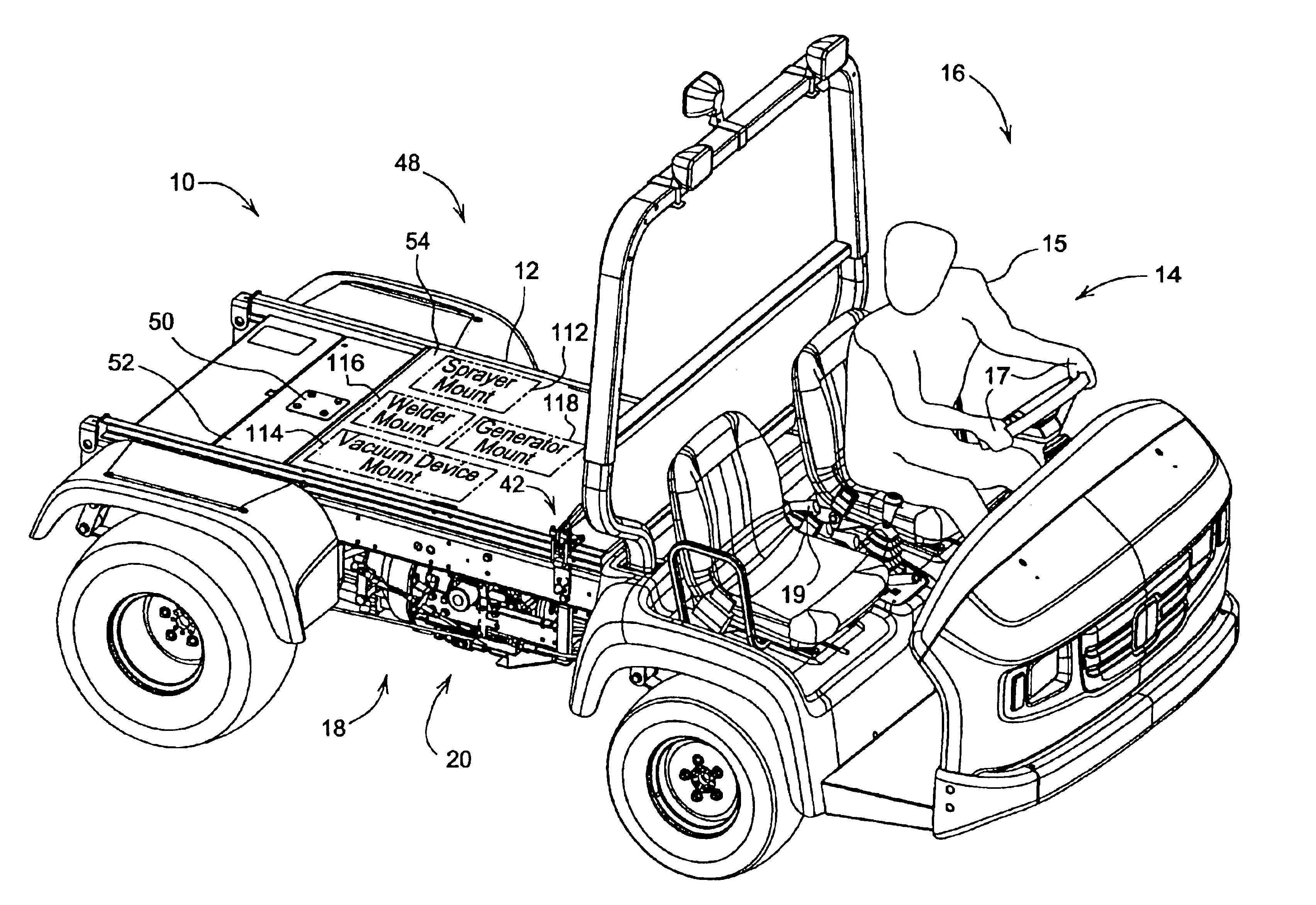
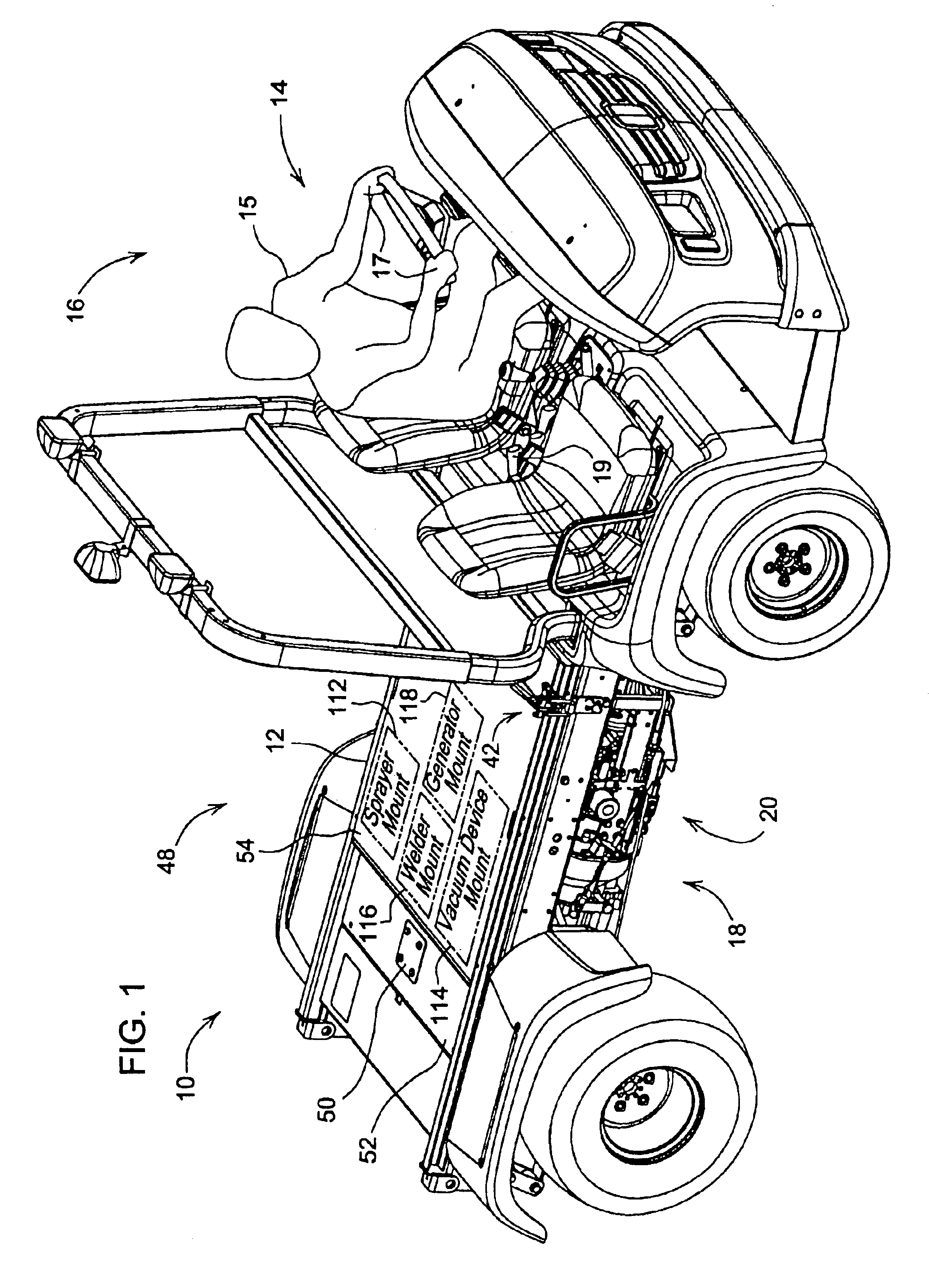
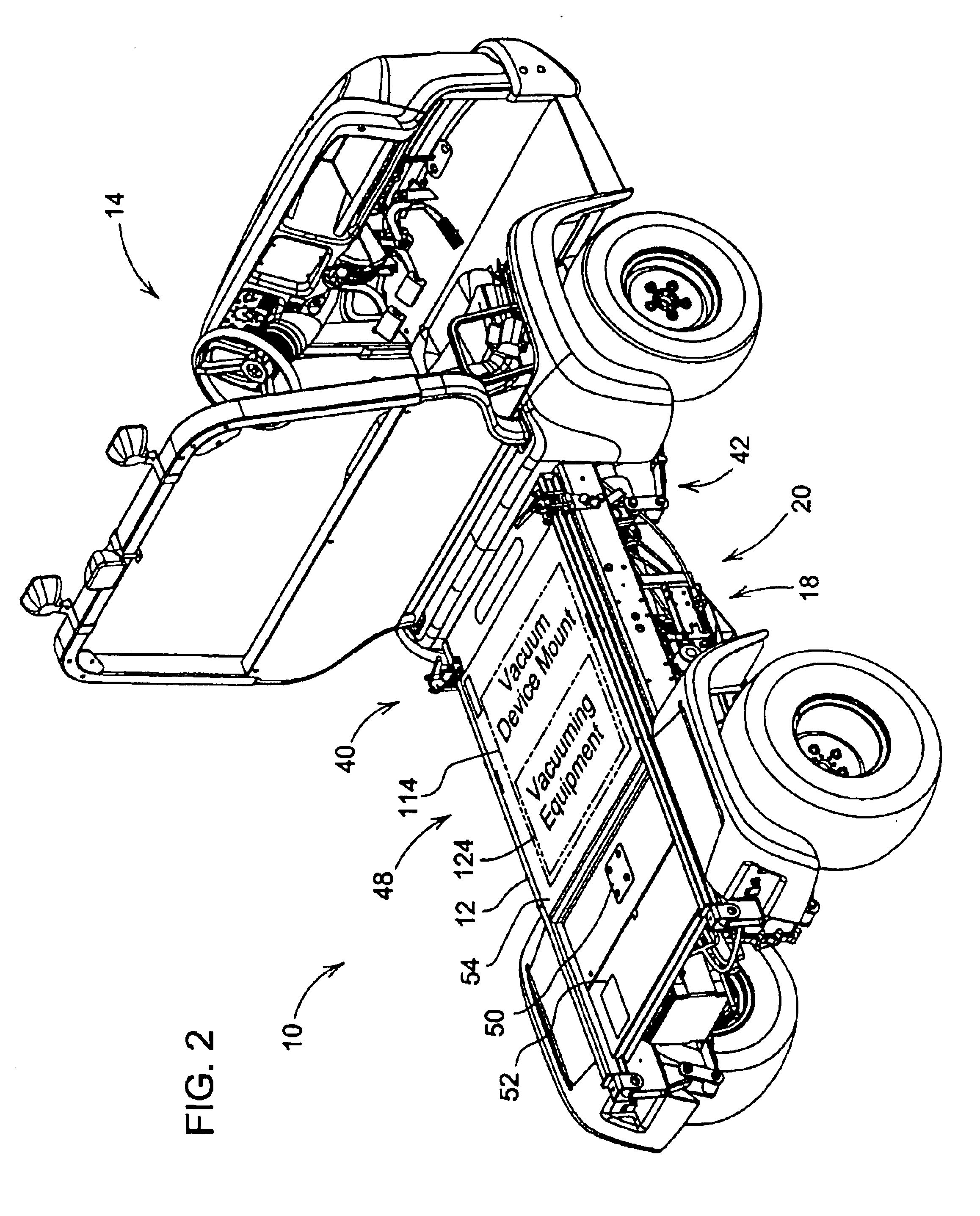
[0028]The present invention generally pertains to utility vehicles. More specifically, the present invention pertains to utility vehicles having a multi-purpose platform for mounting different attachments or equipment to be carried by the vehicles.

[0029]The present invention also pertains to multi-purpose platforms for utility vehicles in which the platforms can be easily raised and lowered while an attachment remains mounted to the platform. The present invention further pertains to methods relating to the utility vehicles and multi-purpose platforms. The present invention can be used, for example, as a turf maintenance utility vehicle. However, the present invention can be embodied in many different forms.

[0030]FIGS. 1 and 2 show a utility vehicle 10 having a multi-purpose platform 12 according to the principles of the present invention. The utility vehicle 10 can be based on a John Deere utility vehicle, such as the highly regarded John Deere PROGATOR™ vehicle, for example. The J...


PUM


Abstract

A utility vehicle for removably mounting and carrying a plurality of different equipment, such as turf maintenance equipment, is provided. The utility vehicle is motorized and has a support frame. A multi-purpose platform is mounted to the support frame. The multi-purpose platform has a plurality of different equipment mounts so configured and arranged to removably mount the plurality of different equipment to the multi-purpose platform. A hydraulic lifting mechanism pivots the multi-purpose platform upward while the equipment is mounted to the multi-purpose platform to provide access to the area of the vehicle underneath the multi-purpose platform.

Description

CROSS REFERENCE TO RELATED APPLICATION[0001]This application is related to the following commonly owned co-pending patent application: “Multi-Function Utility Vehicle” filed on Aug. 14, 2002, published on Feb. 19, 2004 having U.S. Patent Application Publication No. 10 / 218,983.BACKGROUND OF THE INVENTION[0002]The present invention generally pertains to utility vehicles. More specifically, the present invention pertains to utility vehicles having a multi-purpose platform for mounting different attachments to be carried by the vehicles. The present invention also pertains to multi-purpose platforms for utility vehicles in which the platforms can be easily raised and lowered while an attachment remains mounted to the platform. The present invention further pertains to methods relating to the utility vehicles and multi-purpose platforms. The present invention can be used, for example, as a turf maintenance utility vehicle.[0003]Small, motorized utility vehicles, such as John Deere utilit...

Claims


Application Information

Patent Timeline
Patent Type & Authority Patents(United States)
IPC IPC(8): B60P1/00B60P1/64
CPCB60P1/00B60P1/64
Inventor HANSEN, LOREN F.HOMEWOOD, STEPHANIE L.DEVES, THOMAS J.
Owner DEERE & CO
Why Eureka
Try Eureka