Image reader

a reading device and image technology, applied in the direction of instruments, material analysis, solid-state devices, etc., can solve the problem that the image read line sa cannot be illuminated uniformly

Inactive Publication Date: 2005-07-12
ROHM CO LTD
View PDF6 Cites 24 Cited by
  • Summary
  • Abstract
  • Description
  • Claims
  • Application Information

AI Technical Summary

Benefits of technology

[0010]With this structure, light emitted from the light sources travels within the individual sections before reaching the image read line. Therefore, unlike the prior art apparatus, the degree of light overlapping at a longitudinally central portion of the image read line does not differ much from that at the longitudinally opposite ends of the image read line. Therefore, the image read line can be illuminated longitudinally uniformly to enhance the image reading quality.
[0027]Preferably, the case may include a groove for receiving the lens array, and part of the complementary member may be disposed between the lens array and the image read line to prevent the lens array from coming out of the groove. With this structure, it is possible to fix the lens array appropriately and reliably without increasing the number of parts of the image reading apparatus.

Problems solved by technology

However, the above-described prior art structure has a problem that the image read line Sa cannot be illuminated uniformly, as will be described below.

Method used


Image

  • Image reader
  • Image reader
  • Image reader

Examples


Embodiment Construction

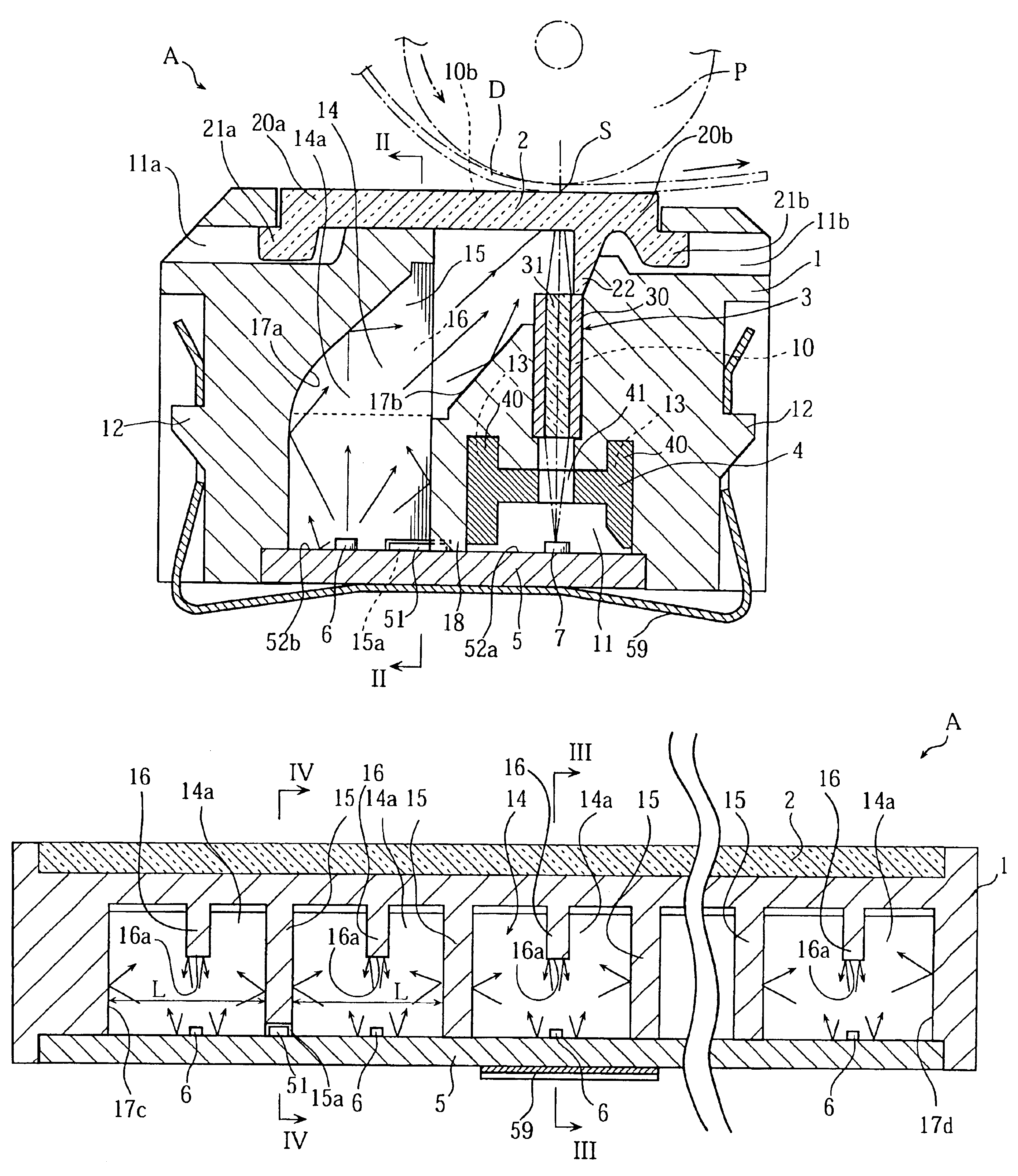
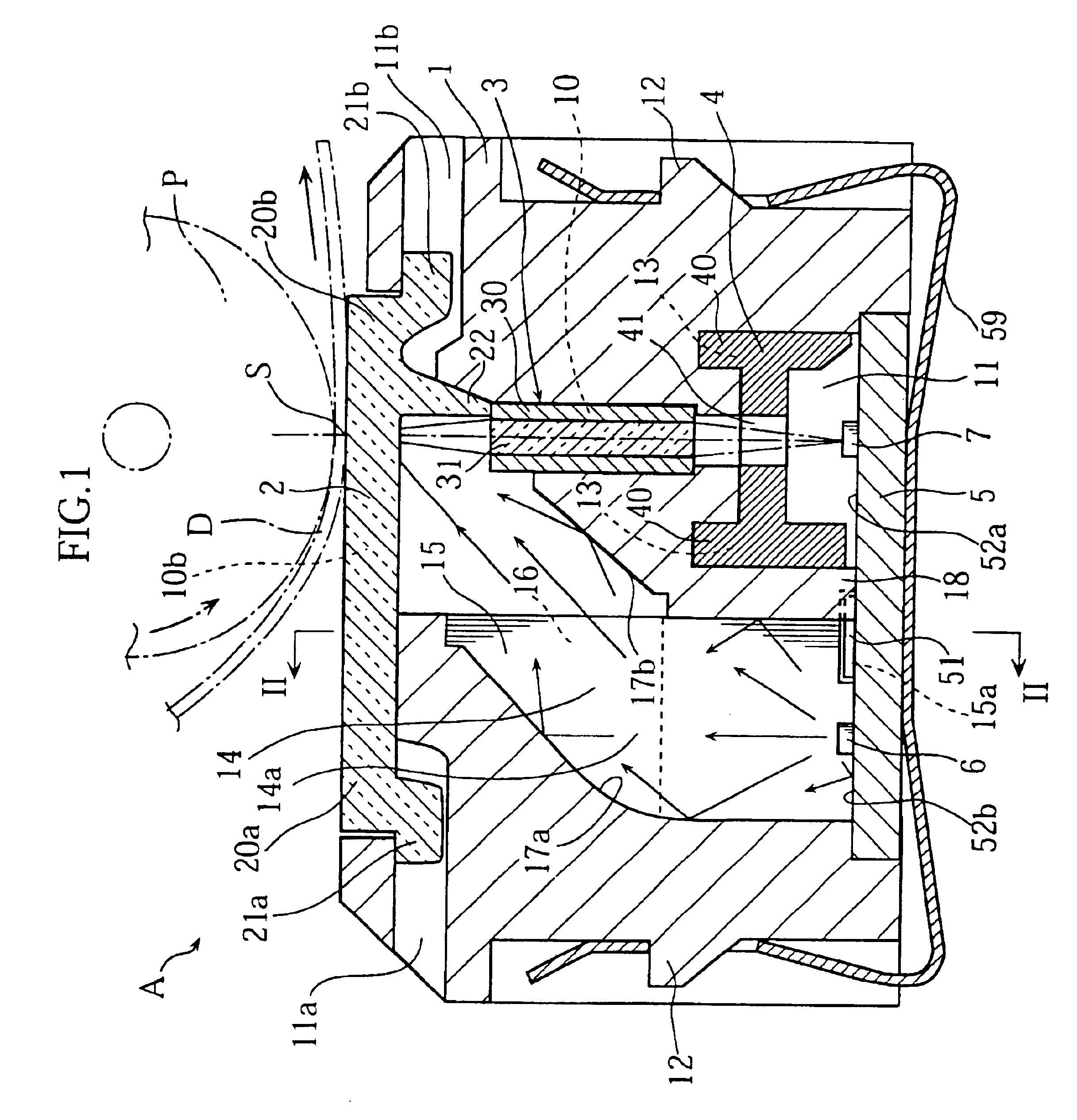
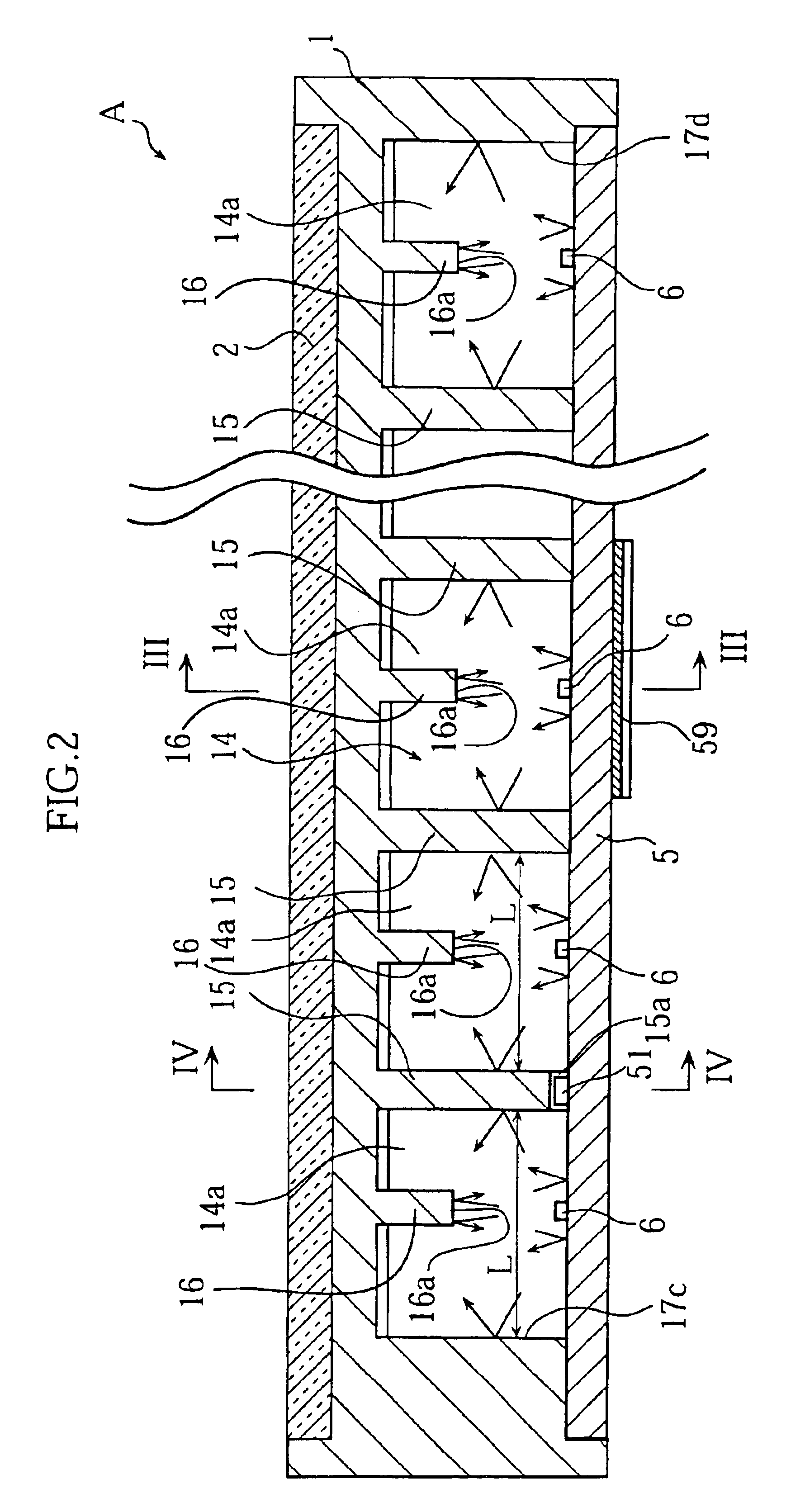
[0041]Preferred embodiments of the present invention will be described below with reference to the accompanying drawings. FIGS. 1 through 5 illustrate a first embodiment of the present invention. As shown in FIG. 1, an image reading apparatus A in this embodiment comprises a case 1, a transparent plate 2, a lens array 3, a reflection preventing member 4, a substrate 5, a plurality of LED chips 6, a plurality of light receiving elements 7 and a plurality of attachments 59.

[0042]The case 1 is elongated as shown in FIG. 5. The case 1 may be made of white synthetic resin prepared by adding titanium oxide to polycarbonate for example. Therefore, all surfaces of the case 1 are white. Thus, the case 1 has a high light reflectivity of 90˜98% for example.

[0043]The transparent plate 2, which may be made for example of acrylic synthetic resin having high transparency, is in the form of a generally elongated rectangle. The transparent plate 2 has an opposite pair of longitudinal edges 20a, 20b ...


PUM


Abstract

An image reader (A) includes a plurality of light sources (6) arranged in line, the light from which travels through a channel (14) and irradiates a linear read area (S). The channel (14) is divided into a plurality of sections (14a) by a plurality of partitions (15). Thus, uniform brightness is obtained in the whole part of the linear read area (S), including both ends and the central part.

Description

TECHNICAL FIELD[0001]The present invention relates to an image reading apparatus used for reading images of various kinds of documents.BACKGROUND ART[0002]A typical prior art image reading apparatus has such a structure as shown in FIG. 11. The illustrated image reading apparatus comprises a substrate 92 provided with a plurality of light sources 91, a lens array 93, a plurality of light receiving elements 94 and a case 90 for housing these components. The case 90 has an upper surface on which a transparent plate 97 is mounted. The transparent plate 97 has an obverse surface a portion of which serves as an image read line Sa. As shown in FIG. 12, the light sources 91 are arranged in a row. The case 90 includes a hollow portion 96 for guiding light emitted from the light sources 91 toward the image read line Sa.[0003]In this image reading apparatus, when light emitted from the light sources 91 impinges on the image read line Sa, the light is reflected by the document D. The reflected...

Claims


Application Information

Patent Timeline
Patent Type & Authority Patents(United States)
IPC IPC(8): H04N1/03H04N1/031
CPCH04N1/031H04N1/40
Inventor ONISHI, HIROAKIKISHIMOTO, TOKIHIKOFUJIMOTO, HISAYOSHI
Owner ROHM CO LTD
Why Eureka
Try Eureka