
Fire protection apparatus and method

Inactive Publication Date: 2005-07-19
ROBINSON JR EDWARD L
View PDF13 Cites 12 Cited by
  • Summary
  • Abstract
  • Description
  • Claims
  • Application Information

AI Technical Summary

Benefits of technology

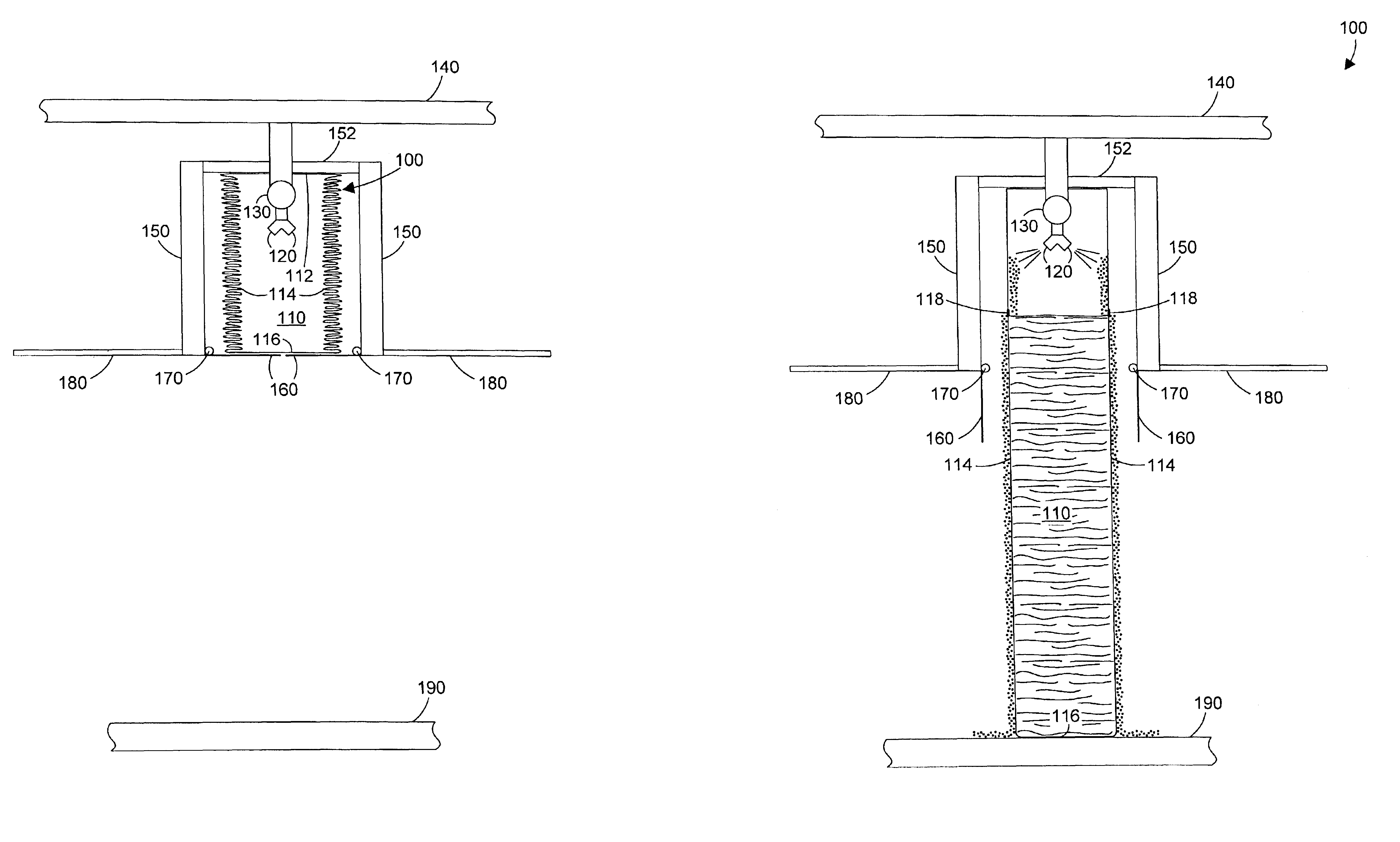
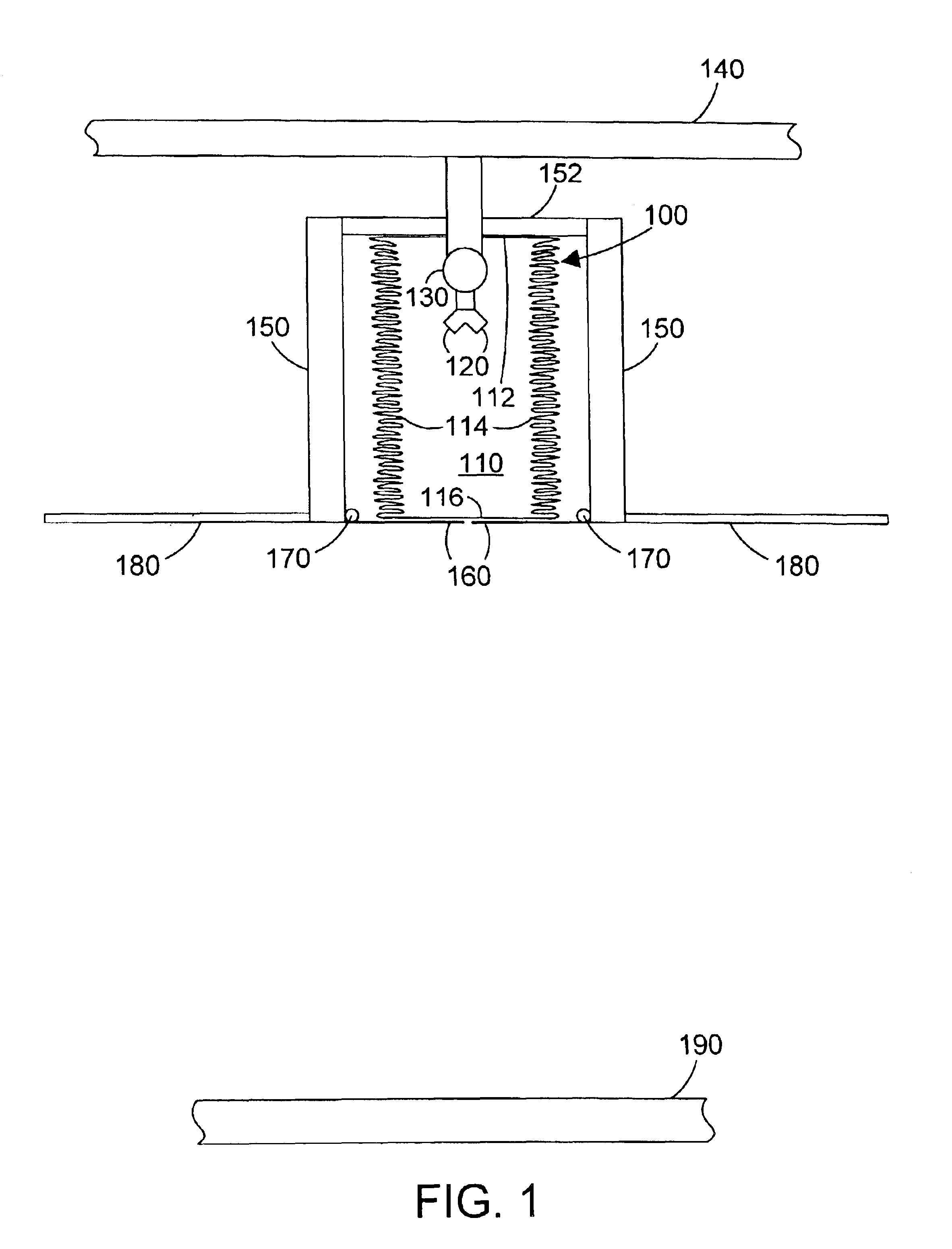
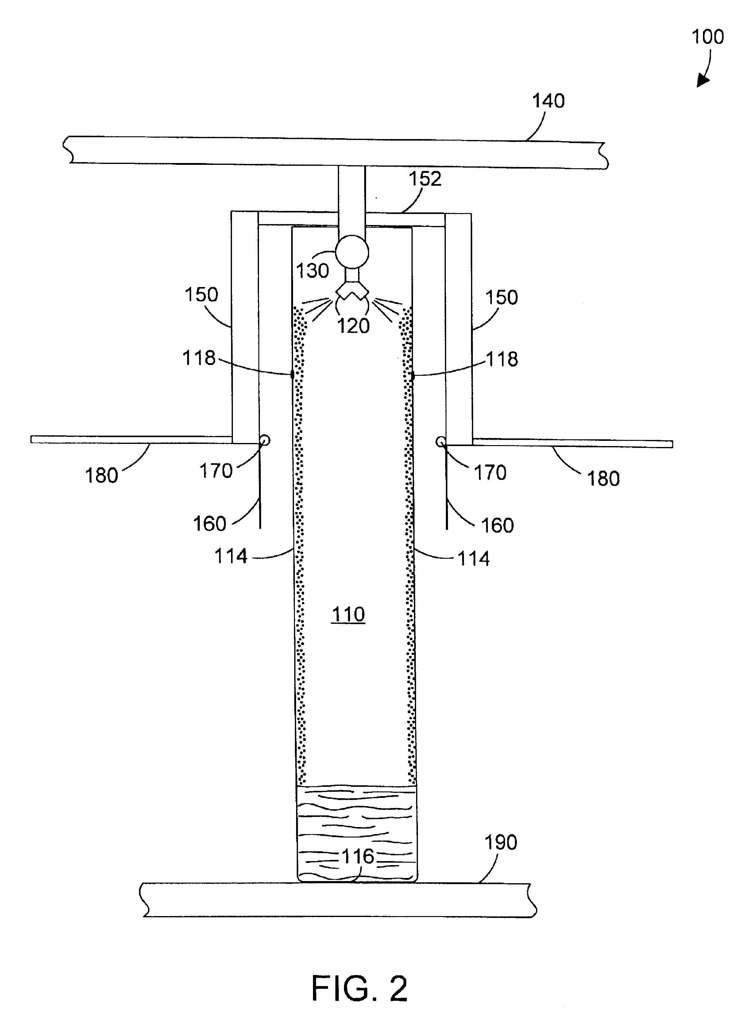
[0008]According to the preferred embodiments, a fire protection apparatus includes a plurality of bladders that are substantially filled with a non-flammable liquid via a manifold that is coupled to a source of non-flammable liquid. The manifold includes one or more nozzles that discharge the non-flammable liquid into each of the plurality of bladders. In one specific embodiment, the apparatus is initially in a substantially collapsed state at or near a ceiling. When fire or smoke is detected, the non-flammable liquid flows into the manifold. As the plurality of bladders begin to fill with non-flammable liquid, the weight of the filling bladders causes the fire protection apparatus to deploy, spanning from ceiling to floor. The bladders may include one or more discharge orifices that allow the non-flammable liquid to flow o

Problems solved by technology

One significant problem with the fire curtain disclosed in the '699 patent occurs when water flow stops.
Oftentimes during a fire, a sprinkler system will function for a short period of time, but the fire itself or a collapsing structure can cause the sprinkler system to fail.
Thus, once the water system fails, the fire curtain would quickly fail as well.
Another problem with the fire curtain in the '699 patent is that it is a single, hollow baffle that spans from ceiling to floor between two walls, and thus provides a barrier to persons who may need to pass.
The '699 fire curtain may serve to retard the spread of a fire, but will also inhibit the evacuation of people.

Method used


Image

  • Fire protection apparatus and method
  • Fire protection apparatus and method
  • Fire protection apparatus and method

Examples


Embodiment Construction

[0024]The preferred embodiments provide a fire protection apparatus that substantially fills with a non-flammable liquid (such as water) and thereby provides a barrier to the spread of fire and smoke. When the term “water” is used herein, it is used as one specific non-flammable liquid that may be used within the scope of the preferred embodiments, which expressly extend to any non-flammable liquid. In one specific embodiment, the apparatus includes a plurality of bladders that are initially in a substantially collapsed position, preferably in an overhead area. When a fire alarm sounds, water is directed through a manifold, which directs the water into each bladder. The weight of the water filling the bladders causes the apparatus to deploy downward until the bottom portions of the bladders contact some surface, creating a barrier that inhibits the spread of fire and smoke. In a second specific embodiment, an apparatus is placed in a stationary position, and water is then directed i...


PUM


Abstract

A fire protection apparatus includes a plurality of bladders that are substantially filled with a non-flammable liquid via a manifold that is coupled to a source of non-flammable liquid and includes one or more nozzles that discharge the non-flammable liquid into each of the plurality of bladders. In one specific embodiment, the apparatus is initially in a substantially collapsed state at or near a ceiling. When fire or smoke is detected, the non-flammable liquid flows into the manifold. As the plurality of bladders begin to fill with non-flammable liquid, the weight of the filling bladders causes the fire protection apparatus to deploy, spanning from ceiling to floor. The bladders may include one or more discharge orifices that allow the non-flammable liquid to flow out of the bladder and down the exterior of the bladder once the bladder is filled to the level of its discharge orifices. In another embodiment, stationary bladders may be placed in walls, such as between buildings or between rooms in a building, to provide fire protection. These stationary bladders are filled using a manifold similar to the deployable embodiment until the bladders are substantially full. In both embodiments, the bladders may include separations between one or more of the bladders that allow a person to pass through the fire protection apparatus, if needed.

Description

BACKGROUND OF THE INVENTION[0001]1. Technical Field[0002]This invention generally relates to the field of fire protection, and more specifically relates to apparatus and methods for inhibiting the spread of fire and smoke.[0003]2. Background Art[0004]Various fire protection devices are known in the art. For example, fire doors have been used to inhibit the spread of fire between different parts of a building. When a fire alarm sounds, fire doors are typically shut and are not to be opened until the threat of fire has been eliminated.[0005]Some devices in the prior art provide a curtain that inhibits the spread of fire. For example, one example of a prior art fire curtain is shown in U.S. Pat. No. 5,809,699 “Fire Curtain”, issued on Sep. 22, 1998 to Joly. The '699 patent discloses a two-walled curtain that deploys from a ceiling. Water is sprayed from the top of the curtain between the two walls onto the inside surface of the two walls. The water runs down inside surface of the walls...

Claims


Application Information

Patent Timeline
IPC IPC(8): A62C2/10A62C2/00
CPCA62C2/10E06B9/0692
Inventor ROBINSON, JR., EDWARD L.
Owner ROBINSON JR EDWARD L
Learn More