Huber needle with anti-rebound safety mechanism

a safety mechanism and huber needle technology, applied in the field of medical needle devices, can solve the problems of huber needles being stuck on the huber needle rebound, requiring a large amount of force during huber needle withdrawal to overcome the resistance of the port's septum, and presenting a high risk of pathogen transmission, so as to prevent needle-stick injuries

Inactive Publication Date: 2005-07-19
ACACIA INC
View PDF65 Cites 78 Cited by
  • Summary
  • Abstract
  • Description
  • Claims
  • Application Information

AI Technical Summary

Benefits of technology

[0011]The present invention specifically addresses and alleviates the above-referenced deficiencies associated with the use of the Huber needle guards of the prior art. More particularly, the present invention is an improved, passive safety needle device featuring a sheath assembly which is outwardly deployable relative to the exposed portion of its affixed needle. By such deployment, a physical barrier can be placed around the needle by the sheath assembly to protect a user from being inadvertently stuck by the needle, thus preventing needle-stick injuries and all the risks that are associated with them. Although this sheath assembly is intended to be used for Huber needle applications, it is specifically recognized herein that such sheath assembly may be used in conjunction with other types of conventional needle applications as well.
[0022]The knob member allows the user to control the movement of the sheath assembly along the elongated groove. This is possible due to the mechanical connections with the proximal tip component of the sheath assembly and the biasing member. Because the preferred biasing member comprises a torsional biasing member which is configured to naturally urge the sheath assembly towards the extended position, the user may utilize the knob member to control the sheath assembly when moving along that direction. In the preferred embodiment, the biasing member comprises either a torsional arm or torsional spring. However, other types of biasing members are contemplated as they may also achieve the ultimate objective of passively deploying the sheath assembly outwardly with respect to the distal needle portion.

Problems solved by technology

More specifically, a great deal of force is required during Huber needle withdrawal to overcome the resistance of the port's septum.
Since a non-dominant hand is typically used in this process to secure the implanted port, it often becomes stuck on the rebound of the Huber needle.
Because a Huber needle is utilized for venous access, such needle-stick injury as described above presents a high risk for pathogen transmission.
However, these home-made guards are not user-friendly as the health-care workers must make the conscious choice to wear them every time an injection is made.
The health-care workers may sometimes neglect to put them on because they are either inconvenient to use, interfere with the process of administering the Huber needle or the health-care workers may just simply forget to wear them.
All of these factors contribute to negating the guards' effectiveness to protect the health-care workers against the dangers of needle-stick injuries.

Method used


Image

  • Huber needle with anti-rebound safety mechanism
  • Huber needle with anti-rebound safety mechanism
  • Huber needle with anti-rebound safety mechanism

Examples


Embodiment Construction

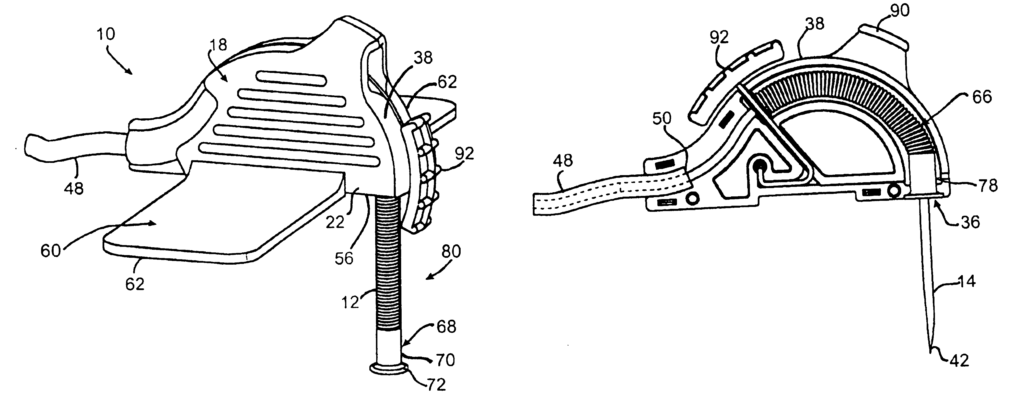
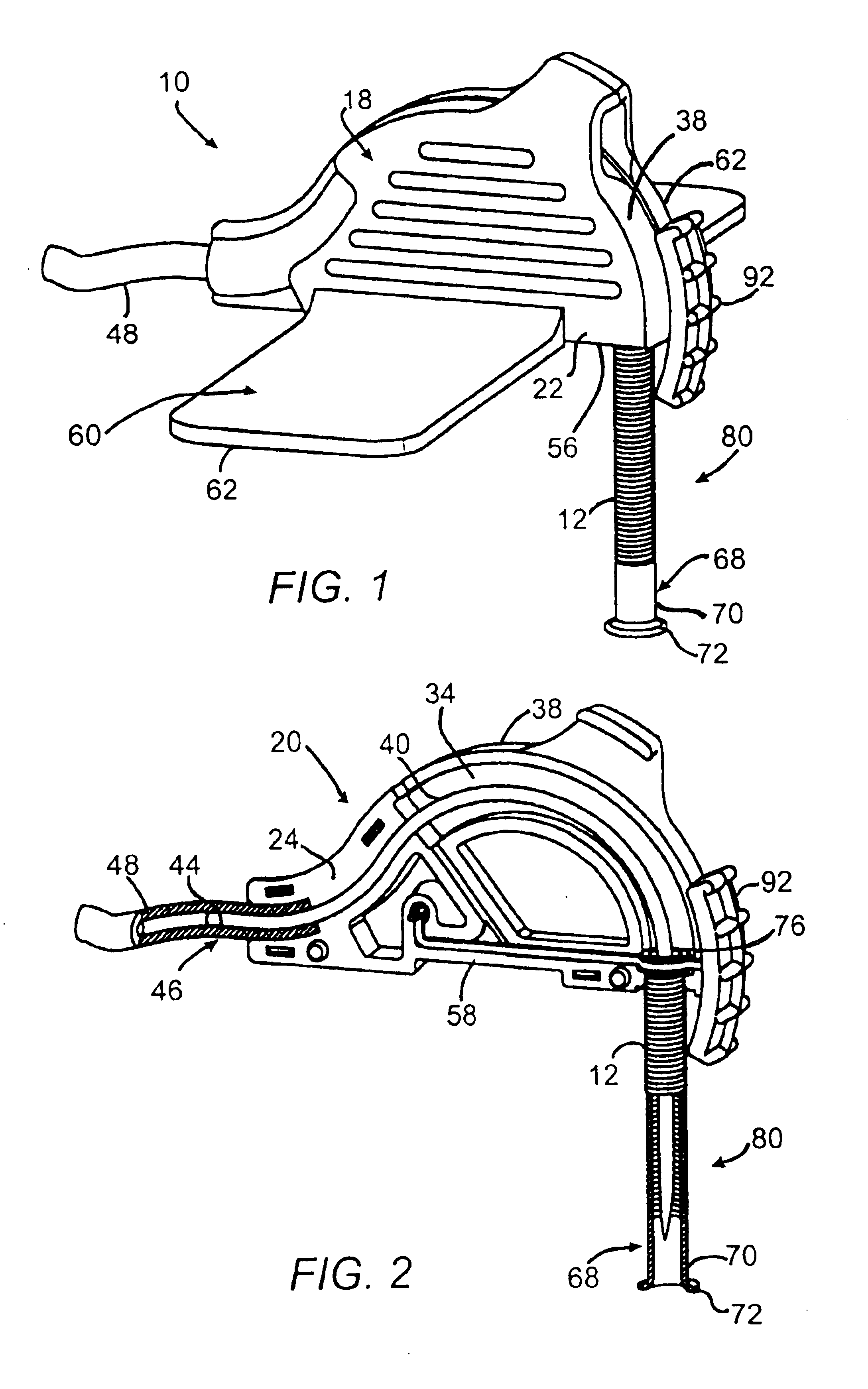
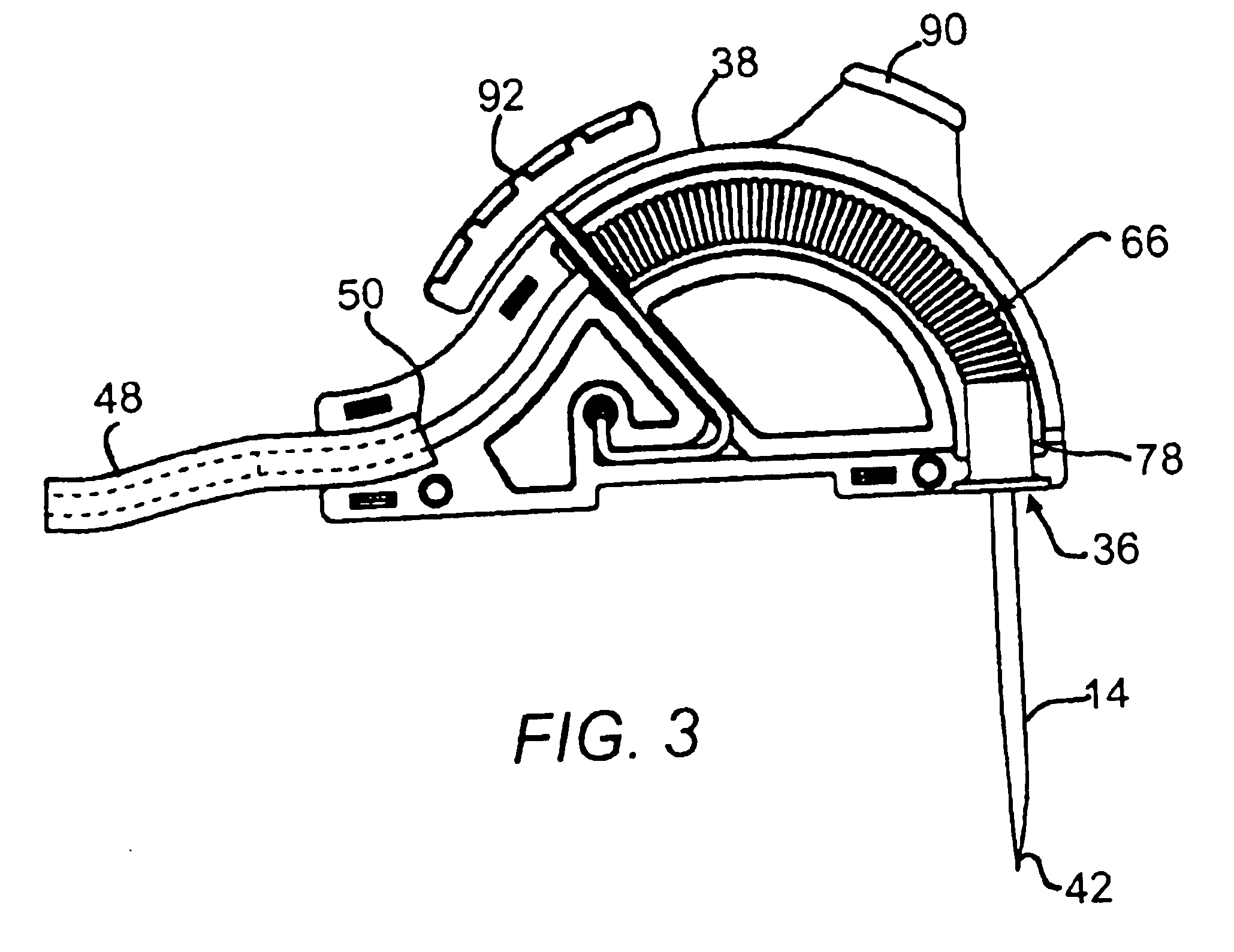
[0055]Referring now to the drawings wherein the showings are for purposes of illustrating preferred embodiments of the present invention only, and not for purposes of limiting the same, FIG. 1 illustrates a passive safety needle device 10 constructed in accordance with a preferred embodiment of the present invention. As indicated above, the present safety needle device 10 features a sheath assembly 12 which is outwardly deployable with respect to the distal needle portion 14, that is, the exposed portion of its affixed needle 16 which is used to access an IV port implanted underneath a patient's designated skin area (not shown).

[0056]As will be soon discussed, such passive deployment of the sheath assembly 12 provides a tangible physical barrier around the distal needle portion 14 to protect a user from being inadvertently stuck by the needle 16, thereby preventing needle-stick injuries and all the risks associated therewith. Although the sheath assembly 12 is preferably used for Hu...


PUM


Abstract

A safety needle device for protecting a user against a needle-stick injury. This needle device includes a needle housing having a distal housing opening. A needle is disposed within the needle housing and has a distal needle portion which extends away therefrom through the distal housing opening. An elongate sheath assembly surrounds the needle within the needle housing. A trigger member retains the sheath assembly within the needle housing against a force urging the sheath assembly towards the distal housing opening. The trigger member is sized and configured to release the sheath assembly from retention to allow the sheath assembly to transition towards and out of the distal housing opening via the force. This causes the sheath assembly to enclose the distal needle portion and protect the user against the needle stick injury.

Description

CROSS-REFERENCE TO RELATED APPLICATIONS[0001]The present application is a continuation-in-part of U.S. patent application Ser. No. unknown entitled “HUBER NEEDLE WITH ANTI-REBOUND SAFETY MECHANISM” filed Jan. 24, 2003, which claims the benefit of U.S. Provisional Application No. 60 / 360,406 entitled “HUBER NEEDLE WITH ANTI-REBOUND MECHANISM” filed Feb. 28, 2002, the entirety of the disclosures of which are expressly incorporated herein by reference.STATEMENT RE: FEDERALLY SPONSORED RESEARCH / DEVELOPMENT[0002](Not Applicable)BACKGROUND OF THE INVENTION[0003]The present invention relates generally to medical needle devices, and more particularly to an improved, passive safety needle device featuring a sheath assembly which is designed to be outwardly deployable and enclose the exposed portion of an affixed needle therewithin so as to protect its user against inadvertent needle-stick injuries.[0004]Needle-stick injuries are common and are of great concern in today's health-care industry....

Claims


Application Information

Patent Timeline
Patent Type & Authority Patents(United States)
IPC IPC(8): A61M5/158A61M5/14A61M5/32A61MA61M11/00
CPCA61M5/158A61M5/3257A61M5/3271A61M2005/1581Y10S128/919
Inventor FLEURY, MICHAEL T.FERGUSON, FERGIE F.HYUN, DONGCHUL D.
Owner ACACIA INC
Why Eureka
Try Eureka