Monolithic pour joint

a monolithic, pour joint technology, applied in the direction of roads, constructions, paving details, etc., can solve the problems of small decrease in the overall volume of concrete, cracks may occur, large cracks may develop in concrete, etc., to prevent buckling or relative angular or vertical displacement of slabs, prevent unevenness or steps

Inactive Publication Date: 2005-02-17
SHAW LEE A +1
View PDF10 Cites 6 Cited by
  • Summary
  • Abstract
  • Description
  • Claims
  • Application Information

AI Technical Summary

Benefits of technology

[0014] The present invention specifically addresses and alleviates the above-referenced deficiencies associated with contraction joints of the prior art. More particularly, the present invention is an improved, monolithic pour joint that is specifically adapted to prevent shear cracking of adjacently disposed concrete slabs while accommodating slip dowel systems for aiding in the placement of slips dowels within edge portions of adjacent concrete slabs.
[0018] The pour joint of the present invention is configured to be compatible with dowel placement systems due to the inclusion of dowel holes in the forms and due to the generally planar configuration of the vertical panel. Such dowel placement systems may be provided at spaced intervals in the pour joints as a means of preventing buckling or relative angular or vertical displacement of the slabs. A sleeve of the dowel placement system may be mounted on the form by insertion through the dowel hole. A sleeve flange of the sleeve is abutted against and secured to the planar vertical panel with fasteners. A sheath may be inserted into the sleeve with steel or iron dowel rods being advanced into the sheath prior to the pouring of concrete slabs such that the slabs may slide freely during expansion and contraction of the slabs to maintain the slabs in a common plane and thus prevent unevenness or steps from forming at the pour joint.
[0019] A layer of resilient joint filler may be included along a side of the vertical panel. The joint filler may be configured to alternately compress and expand during relative lateral movements of the concrete slabs such as may occur during thermal expansion and contraction. The joint filler prevents the entrapment of stones, debris or other material between the slabs that may otherwise interfere with thermal expansion of the slabs. The joint filler may be fabricated from foam material such as fiber board, closed-cell foam rubber or low density, closed-cell polyethylene foam. An edge cap may also be mounted upon and extend along the upper edge of the form in order to provide protection against water infiltration and particle entrapment within the pour joint. The edge cap may be formed as an extrusion of relatively flexible, elastomeric material such as a plastic material.

Problems solved by technology

During construction of concrete pavement such as for sidewalks, driveways, roads and flooring in buildings, cracks may occur due to uncontrolled shrinkage or contraction of the concrete.
Such cracks are the result of a slight decrease in the overall volume of the concrete as water is lost from the concrete mixture during curing.
Thus, large cracks may develop in concrete where the overall length of the pavement is fairly large.
In addition, the cracks may continue to develop months after the concrete is poured due to induced stresses in the concrete.
Although effective in providing longitudinal contraction joints to prevent random cracking, the checkerboard system of concrete pavement construction is both labor intensive and time consuming due to the need to remove the forms and due to the waiting period between the curing of the first batch and the pouring of the second batch of concrete.
Unfortunately, vertical displacement of adjacent slabs may also occur at a joint due to settling or swelling of the substrate below the slab or as a result of vertical loads created by vehicular traffic passing over the slabs.
Such height differential may result in an unwanted step or fault in a concrete sidewalk or roadway or in flooring of a building creating a pedestrian or vehicular hazard.
Furthermore, such a step may allow for the imposition of increased stresses on the corner of the concrete slab at the joint resulting in degradation and spalling of the slab.
Although the key joint presents several advantages regarding its effectiveness in transferring loads between adjacent slabs, key joints also possess certain deficiencies that detract from their overall utility.
Perhaps the most significant of these deficiencies is that the tongue of the key joint may shear off under certain loading conditions.
Furthermore, the face of the key joint may spall or crack above or below the groove under load.
If the vertical load is applied on the tongue side, the failure will occur at the bottom portion of the groove.
Conversely, if the vertical load is applied on the groove side of the joint, the failure will occur near the upper surface of the slab upon which the load is applied.
Shear failure of the tongue and groove may also occur due to opening of the key joint as a result of shrinkage of the concrete slab.
As the key joint opens up over time, the groove side may become unsupported as the tongue moves away.
Vertical loading of this unsupported concrete causes cracking and spalling parallel to the joint.
Such cracking and spalling may occur rapidly if hard-wheeled traffic such as forklifts are moving across the joint.
Another deficiency associated with key joint systems is related to the size, configuration and vertical placement of the tongue and groove within the key joint.
Such spalls occurring from this type of deficiency typically run the entire length of the longitudinal key joint and are difficult to repair.
Furthermore, key joints suffer from an additional deficiency in that slip dowel systems may not be compatible for use with preformed metallic key joint forms due to interference thereof with a flanged base member of the slip dowel system.
Because slip dowels are typically located near the midheight of a contraction joint, the tongue and groove of the metal form may interfere with the installation of the flanged base member of the slip dowel system.

Method used


Image

  • Monolithic pour joint
  • Monolithic pour joint
  • Monolithic pour joint

Examples


Embodiment Construction

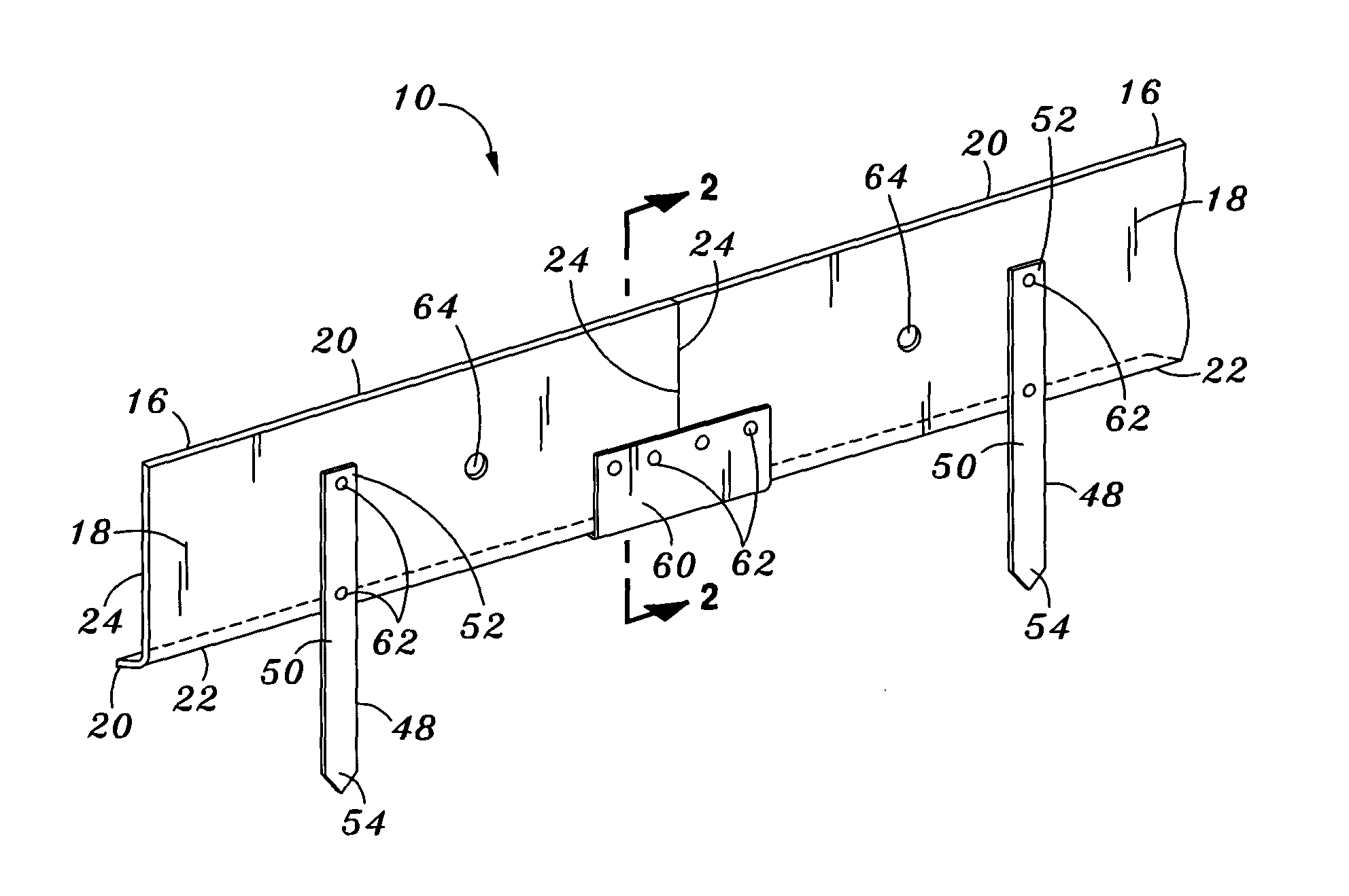
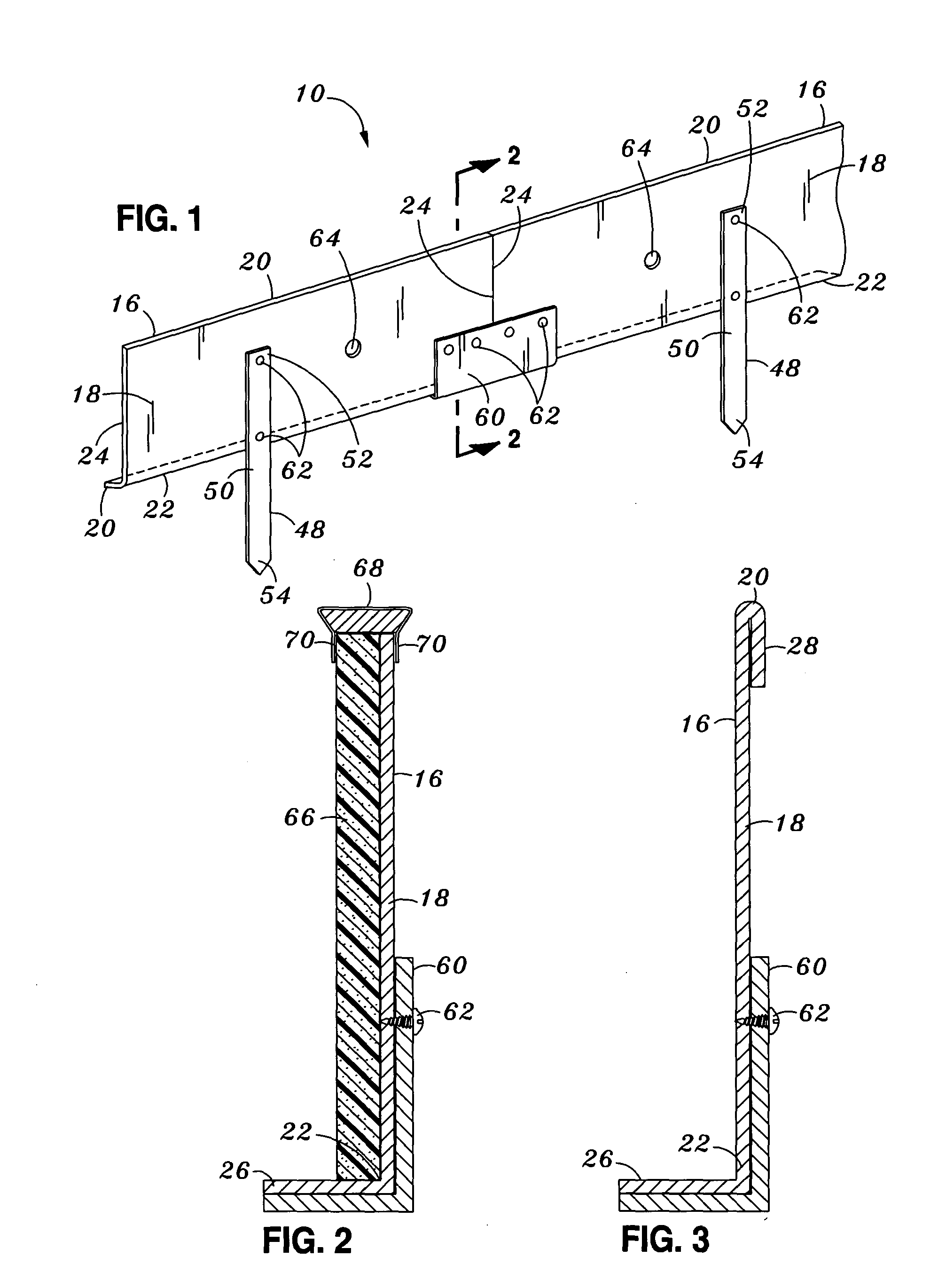
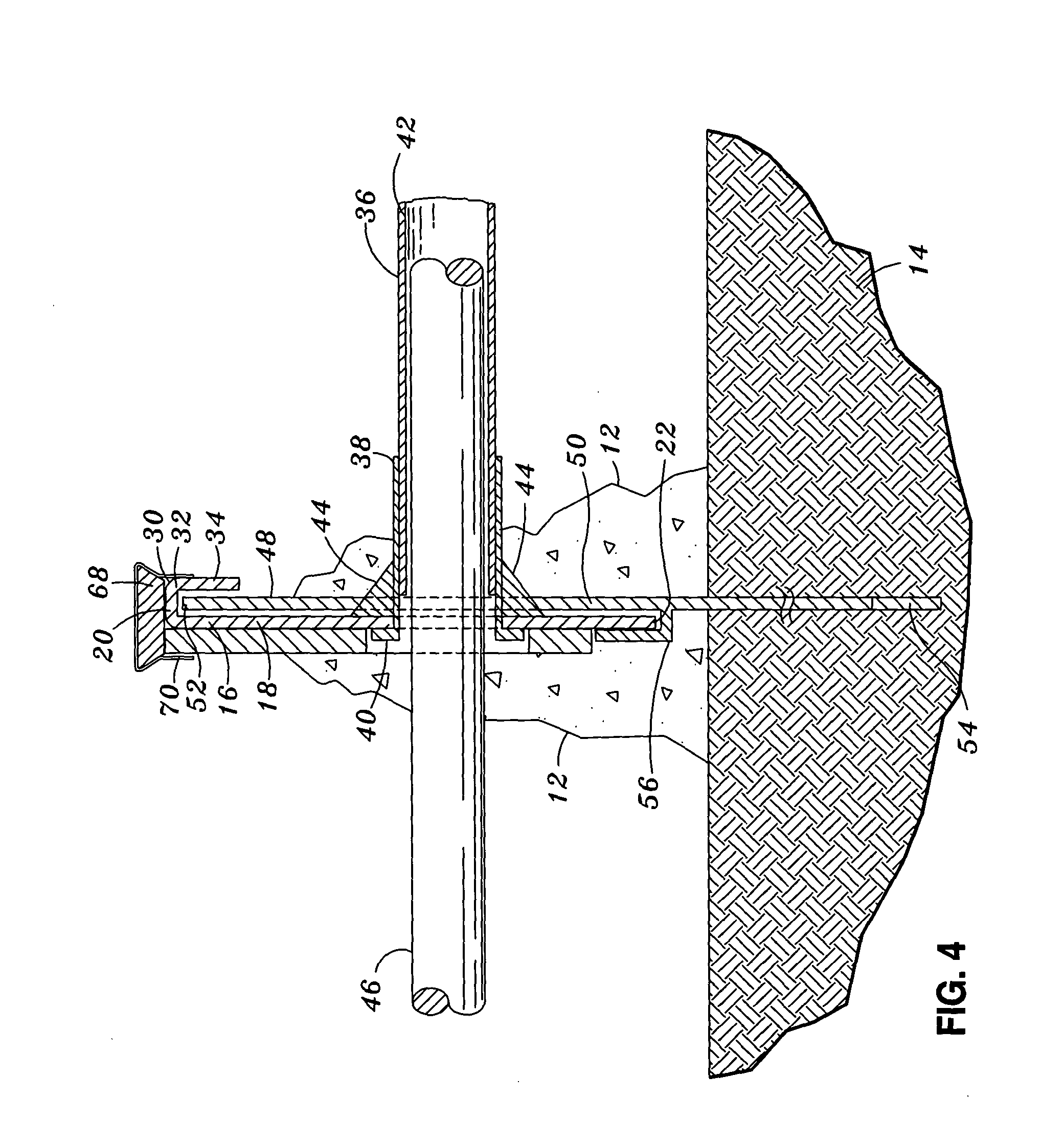
[0028] Referring now to the drawings wherein the showings are for purposes of illustrating preferred embodiments of the present invention and not for purposes of limiting the same, FIG. 1 illustrates a monolithic pour joint 10 of the present invention wherein the pour joint 10 may be interposed between concrete slabs 12 that are disposed above a subgrade or a substrate 14. The substrate 14 may be soil underlying the slab. Alternatively, the substrate 14 may be a metal decking or other underlying surface adapted to support concrete slabs 12. The pour joint 10 is comprised of at least one elongate form 16 or a plurality of forms 16 arranged in end-to-end alignment with a splice 60 interconnecting the forms 16 and a plurality of elongate stakes 48 secured to a side of the forms 16 to fixedly maintain or support the forms 16 above the substrate 14.

[0029] Each of the forms 16 includes a substantially planar, vertical panel 18 having an upper edge 20 and a lower edge 22 to define a form ...


PUM


Abstract

There is provided a monolithic pour joint interposed between adjacent concrete slabs disposed on a substrate. The pour joint comprises a plurality of elongate forms interconnected with splices. Each one of the forms has a substantially planar, vertical panel with upper and lower edges and opposing ends respectively defining a form width and a form length. The forms are arranged such that the form lengths are generally aligned end to end. The lower edge of the vertical panel has a base flange extending generally laterally therefrom. A plurality of stakes are disposed in transverse relation to the form width and are secured to a side of the vertical panel at spaced intervals to fixedly maintain the forms in relation to the substrate. The pour joint may include a plurality of dowel holes extending through the vertical panel such that a dowel placement system may be installed in the pour joint.

Description

CROSS-REFERENCE TO RELATED APPLICATIONS [0001] (Not Applicable) STATEMENT RE: FEDERALLY SPONSORED RESEARCH / DEVELOPMENT [0002] (Not Applicable) BACKGROUND OF THE INVENTION [0003] The present invention relates generally to concrete forming equipment and, more particularly, to a uniquely configured monolithic pour joint specifically adapted to prevent shear cracking of adjacently disposed concrete slabs. The pour joints are configured to facilitate the placement of dowel rods within adjacent concrete slabs. [0004] During construction of concrete pavement such as for sidewalks, driveways, roads and flooring in buildings, cracks may occur due to uncontrolled shrinkage or contraction of the concrete. Such cracks are the result of a slight decrease in the overall volume of the concrete as water is lost from the concrete mixture during curing. Typical contraction rates for concrete are about one-sixteenth of an inch for every ten feet of length. Thus, large cracks may develop in concrete wh...

Claims


Application Information

Patent Timeline
Patent Type & Authority Applications(United States)
IPC IPC(8): E01C11/14
CPCE01C11/14
Inventor SHAW, LEE A.SHAW, RONALD D.
Owner SHAW LEE A
Why Eureka
Try Eureka