Multifunctional switch

a multi-functional switch and switch technology, applied in the field of multi-functional switches, can solve the problems of not revealing the inclined surface, the switch of fr 1.537.956 is a bit bulky, and the space requiring construction capable of handling high current and voltage levels

Inactive Publication Date: 2005-07-19
SONION ROSKILDE
View PDF9 Cites 82 Cited by
  • Summary
  • Abstract
  • Description
  • Claims
  • Application Information

AI Technical Summary

Benefits of technology

[0030]Instead of spring-loading the contact member towards the two sets of contact surfaces, the sets of contact surfaces may be spring-loaded towards said contact member. As the contact member is spring-loaded towards the contact member, and as the contact surfaces comprise valleys and inclined surfaces, a certain force is needed to move the contact member between the predetermined positio

Problems solved by technology

However, FR 1.537.956 does not disclose that the inclined surfaces may be connected to external terminals that can provide a change of a program of an instrument, or provide an

Method used


Image

  • Multifunctional switch
  • Multifunctional switch
  • Multifunctional switch

Examples


second embodiment

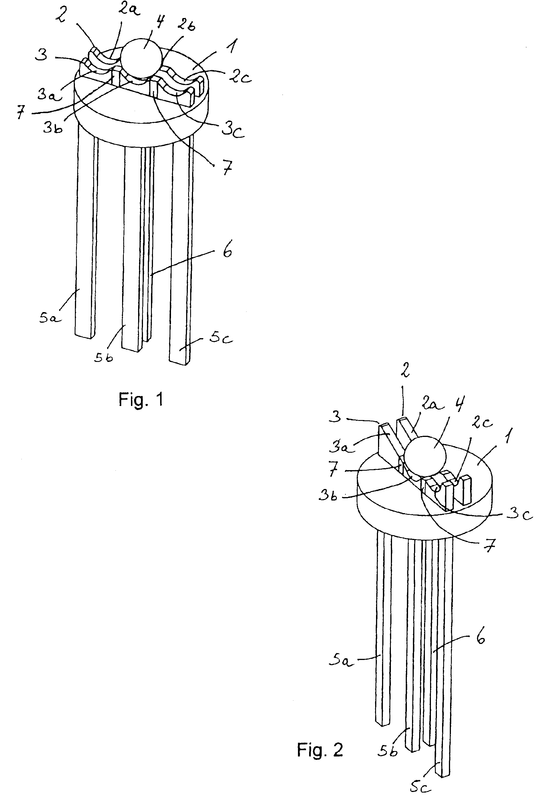
[0051]FIG. 2 shows a second embodiment, which is almost the same embodiment as FIG. 1, however, one pair of corresponding contact surfaces defines inclined surfaces (2a, 3a) along which the contact member 4 slides. The contact member4 may be pushed upwards along the contact surfaces (2a, 3a) for e.g. changing the program or for adjusting the volume of the instrument in which it is integrated. Due to the spring-loading of FIG. 4, the contact member 4 will return to the valley defined by the contact surfaces (2b, 3b) upon being released.

[0052]Instead of having two sets of valleys (2b, 3b and 2c, 3c) and one set of inclined surfaces (2a, 3a), the sets of contact surfaces may comprise two sets of inclined surfaces and one set of valleys positioned between the sets of valleys, or they may comprise only two sets of inclined surfaces.

third embodiment

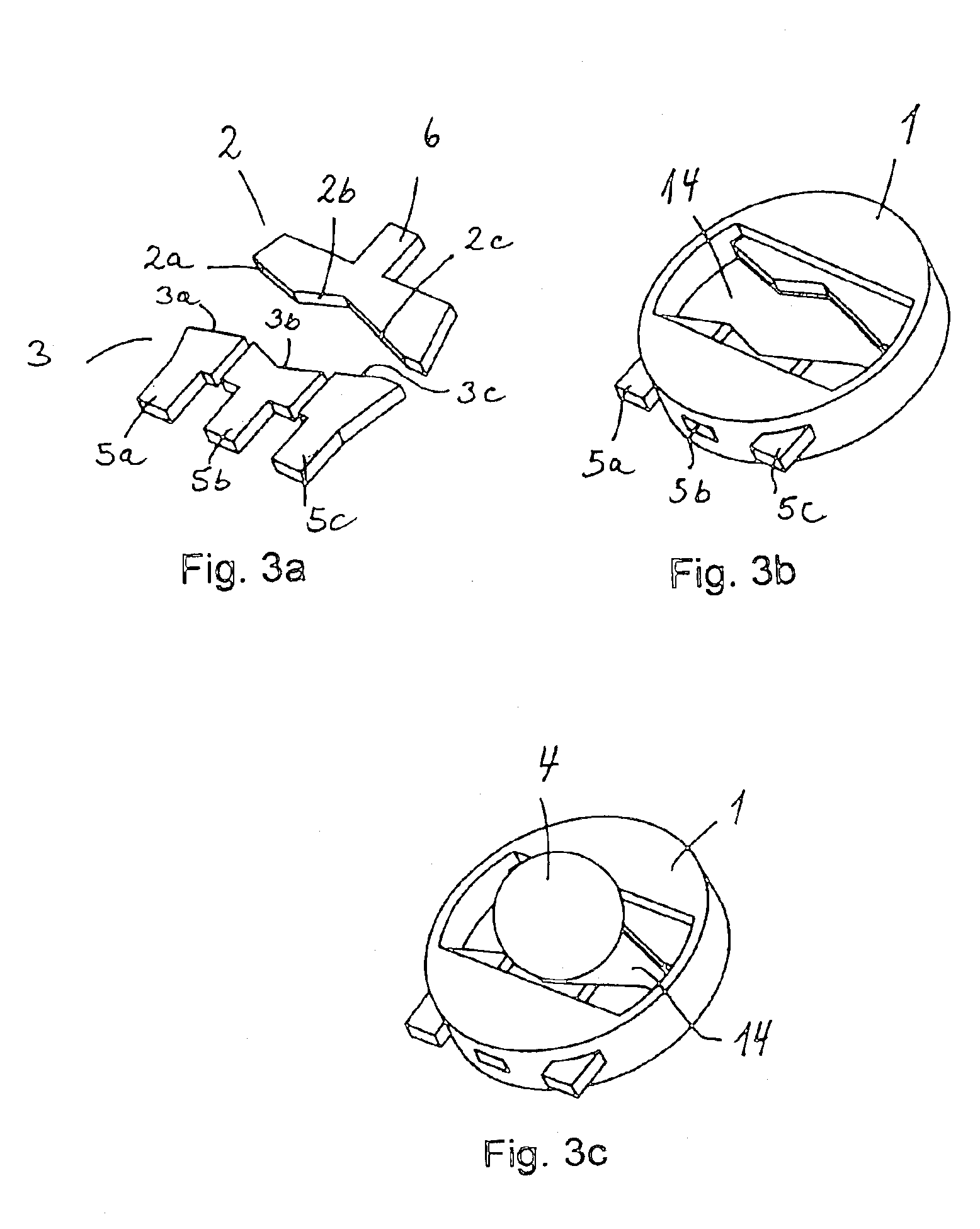
[0053]FIGS. 3a-c show the switch comprising a base part 1 wherein a first (2) and second (3) set of contact surfaces comprising contact surfaces (2a, 2b, 2c) and (3a, 3b, 3c) is provided. The contact surfaces being arranged vertically and not horizontally arranged, as shown in the embodiment of FIGS. 1-2. Thus, the terminals (5a, 5b, 5c, 6) will not be loaded by a vertical pressure generated when switching the contact member. The pairs of corresponding contact surfaces comprise two sets of valleys (2a, 3a and 2c, 3c) and one set of corresponding inclined surfaces (2b, 3b).

[0054]The contact member gains access to the contact surfaces via the groove 14 provided in the base part.

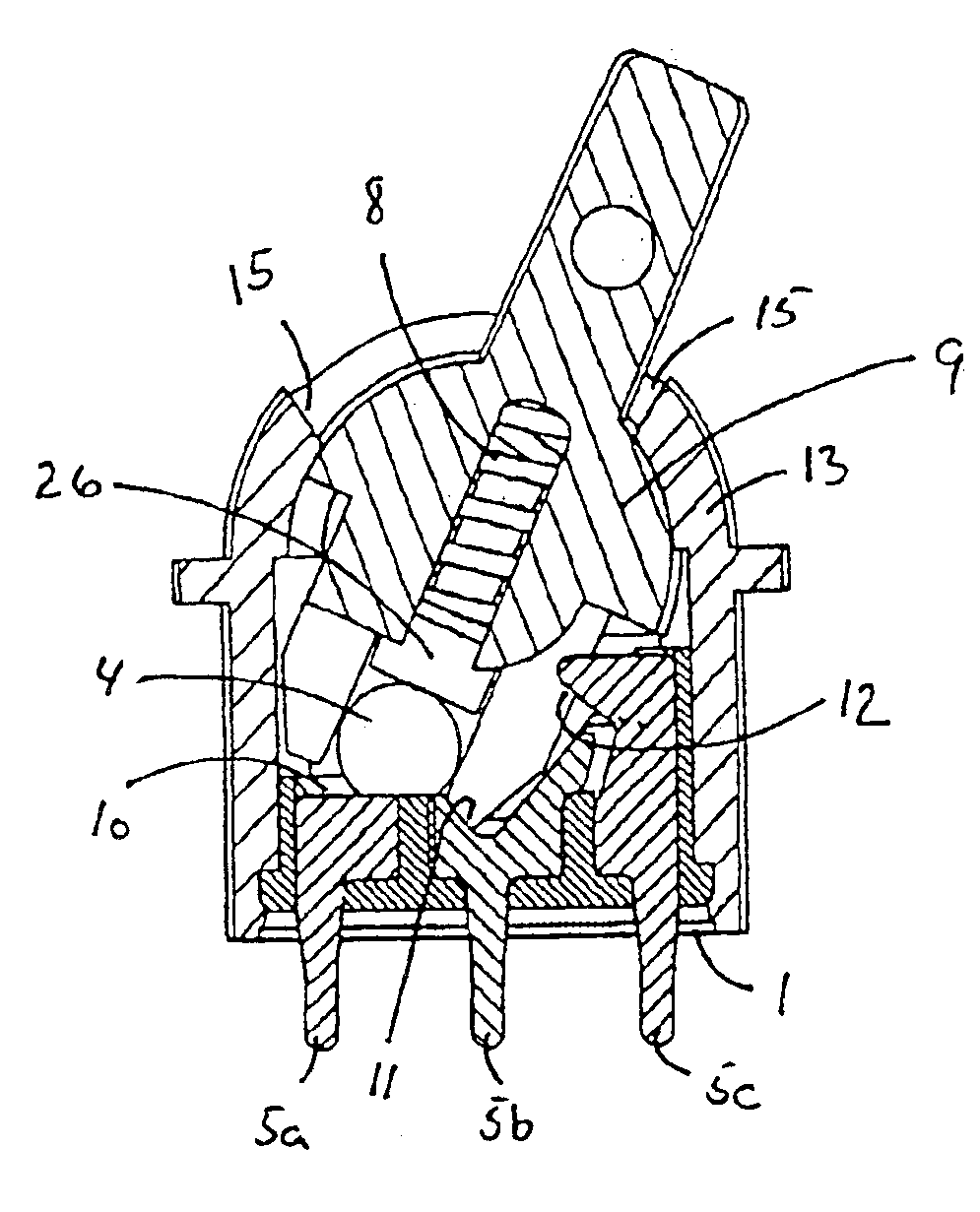
[0055]FIGS. 4a-c show an assembled switch comprising a base part 1, a first / second set of contact surfaces (2,3). The contact member 4 is spring-loaded towards the contact surfaces by means of spring 8 and pressure pad 26 both provided inside a user operable pin 9. The pin may be positioned in three different p...


PUM


Abstract

The present invention relates to a hearing aid multifunctional switch comprising a base part, an externally activable switch arm, and a first and a second set of contact surfaces disposed at a surface of said base part. The first set of contact surfaces is adjacently positioned so as to form a substantially continuous surface, whereas the second set of electrically isolated contact surfaces is adjacently positioned so as to form a substantially continuous surface. The second set of contact surfaces is oppositely arranged to said first set so that the two sets have pairs of corresponding contact surfaces. A contact member is movable between said pairs of contact surfaces for providing electrical contact between a pair of corresponding contact surfaces. A pressure pad, wherein at least part of said pressure pad is positioned between a resilient member and the contact member, is biased by the resilient member against the contact member so as to ensure continuous contact between the contact surfaces and the contact member.

Description

[0001]This application is a continuation-in-part of application Ser. No. 10 / 267,739 filed on Oct. 10, 2002 now abandoned, the entire contents of which are hereby incorporated by reference and for which priority is claimed under 35 U.S.C. § 120.FIELD OF THE INVENTION[0002]The present invention relates to a multifunctional switch for controlling an electrical instrument, such as a hearing instrument or a mobile phone.BACKGROUND OF THE INVENTION[0003]French patent FR 1.537.956 discloses a switch intended for use in relation to control of e.g. a windscreen wiper of a car. FR 1.537.956 provides two sets of valleys each of which set comprises two contact surfaces adjacently positioned and insulated from each other. A valley is formed in each surface, and the valleys are adapted to receive and hold a conducting member (a metallic ball), so that contact is formed, e.g. between two protruding terminals, when the ball connects two conducting surfaces, no contact is formed if one of the surfac...

Claims


Application Information

Patent Timeline
IPC IPC(8): H01H1/12H01H1/16H04R25/00H01H23/00H01H23/14H01H1/20
CPCH01H1/16H01H1/20H01H23/146H01H2011/0043H01H2300/004H04R25/65H04R2225/61H04R25/603
Inventor RAVNKILDE, S.O SLASHED.RENJACOBSEN, TOMAS
Owner SONION ROSKILDE
Why Eureka
Try Eureka