High density fiber distribution frame

a fiber distribution frame and high-density technology, applied in the field of high-density fiber distribution frame, can solve the problems of interference with equipment density, cable troughs and other cable management structures,

Inactive Publication Date: 2005-07-19
COMMSCOPE TECH LLC
View PDF14 Cites 79 Cited by
  • Summary
  • Abstract
  • Description
  • Claims
  • Application Information

AI Technical Summary

Benefits of technology

[0004]The present invention relates to a telecommunications equipment rack with vertical supports on which are located equipment mounting locations, cable troughs for directing cables to and from equipment mounted at the mounting locations, a center channel including cable slack storage structures, a base to which the vertical supports are mounted and a plurality of horizontal braces extending between the vertical supports and connected to a rear wall of the center channel. The connection between the base and each vertical support is reinforced with a triangularly shaped gusset. In addition, an L-shaped gusset extends between the base and the lowest mounted horizontal bracket. The vertical ...

Problems solved by technology

However, adding reinforcements to these known racks may interfere with equipment den...

Method used


Image

  • High density fiber distribution frame
  • High density fiber distribution frame
  • High density fiber distribution frame

Examples


Embodiment Construction

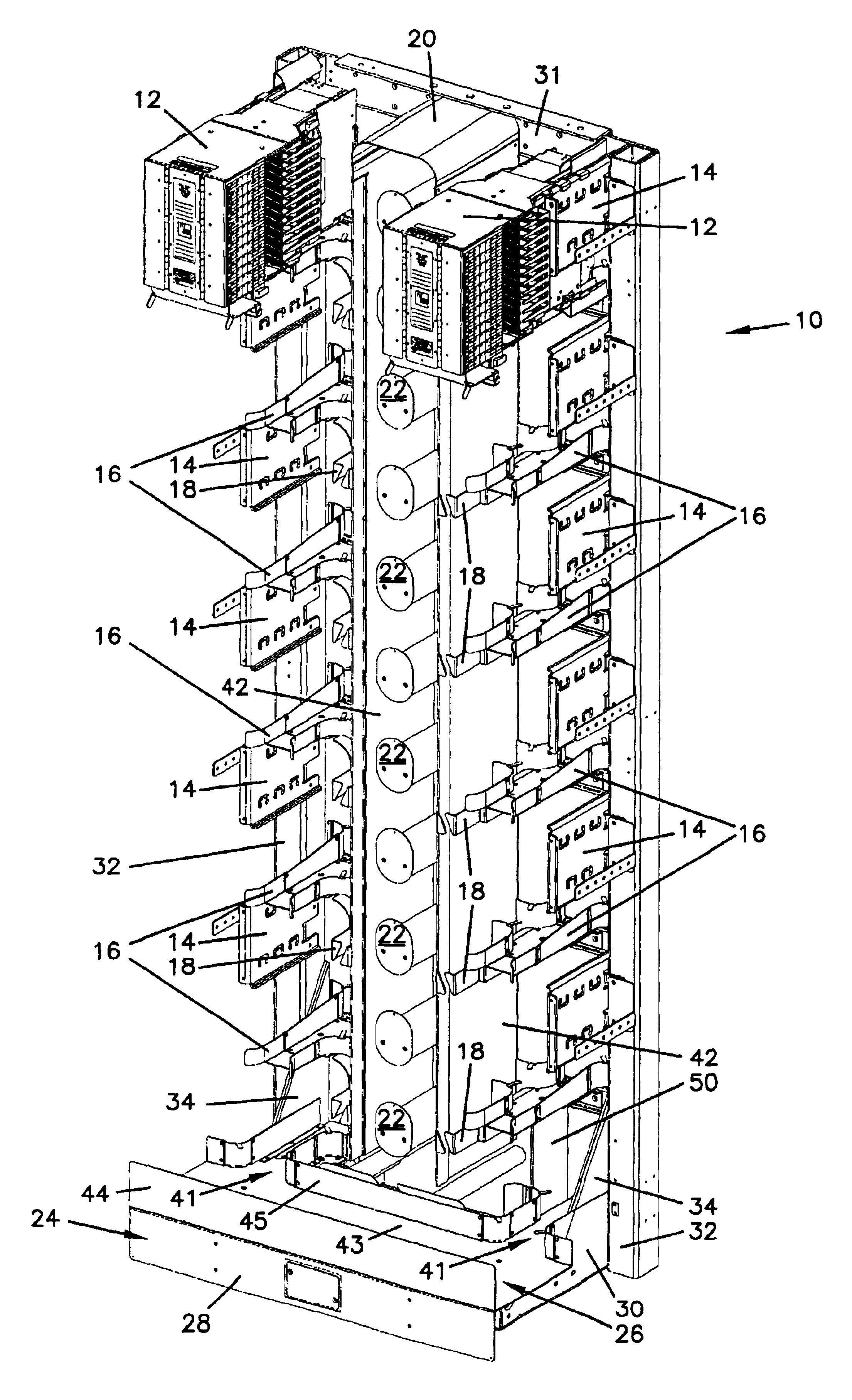
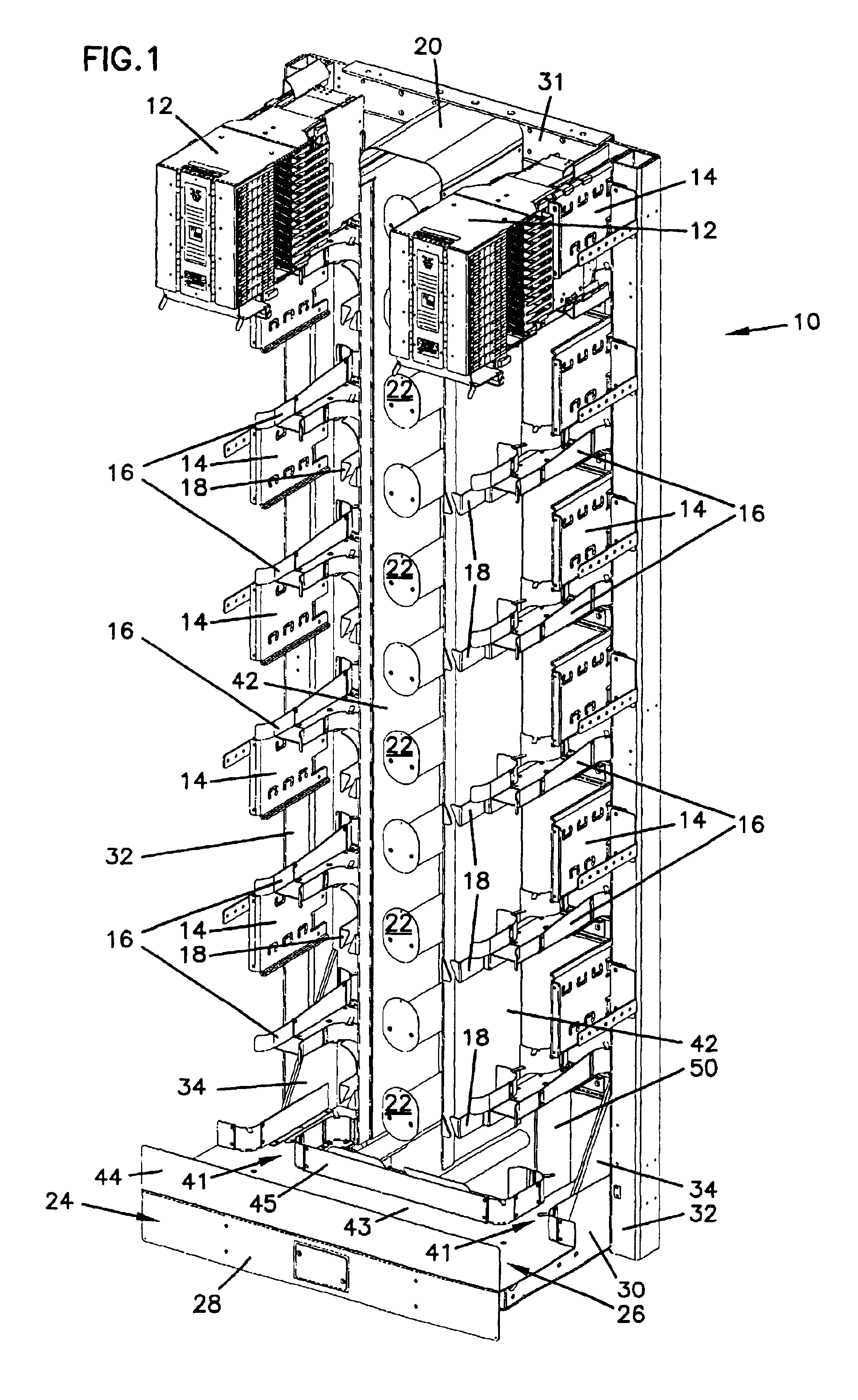
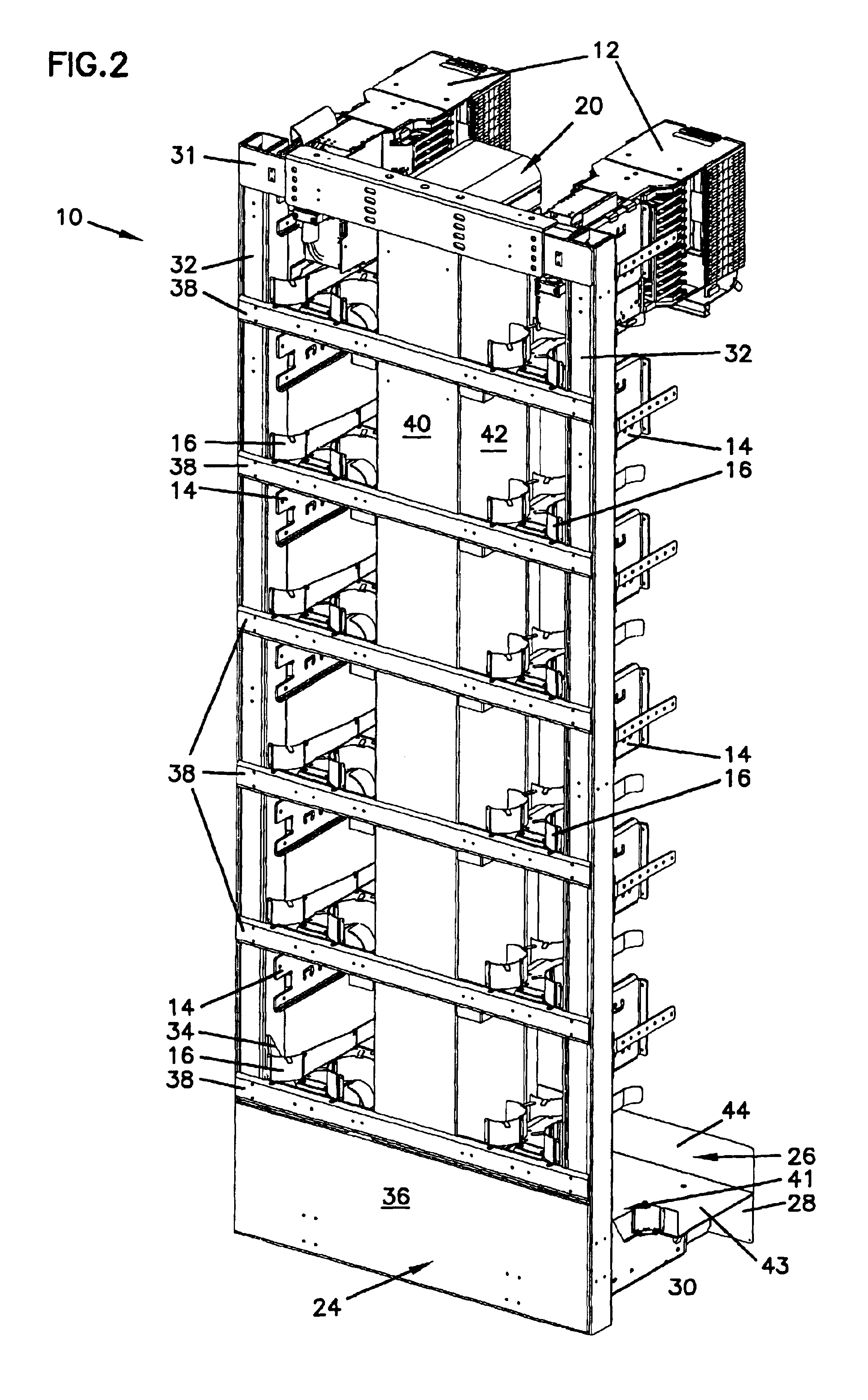
[0034]Reference will now be made in detail to the exemplary aspects of the present invention which are illustrated in the accompanying drawings. Wherever possible, the same reference numbers will be used throughout the drawings to refer to the same or like parts.

[0035]Known racks for mounting telecommunications equipment, such as the optical fiber equipment racks in the patents referenced above, provide relatively dense and scalable solutions for telecommunications installations. Such dense installations need adequate cable troughing associated with the installation to deal with the number of cables leading to and from equipment mounted within the racks. Preferably, these troughs are located in positions which allow for compatibility between cable troughing among adjacent equipment racks.

[0036]In addition to locations of cable management structures, it is desirable that the racks have the ability to withstand dynamic lateral stresses such as might be created by an earthquake. Racks ...


PUM


Abstract

The present invention relates to a telecommunications equipment rack with vertical supports on which are located equipment mounting locations, cable troughs for directing cables to and from equipment mounted at the mounting locations, a base to which the vertical supports are mounted, a triangularly shaped gusset reinforcing the connection between the vertical support and the base, and an L-shaped gusset extending between the base and a horizontal bracket mounted to the vertical supports. The vertical supports are made from two U-shaped channels mounted to form a closed rectangular channel. The present invention further relates to a telecommunications equipment rack with vertical supports on which are located equipment mounting locations, cable troughs for directing cables to and from equipment mounted at the mounting locations, a base to which the vertical supports are mounted, and a lower portion of each vertical forming a triangularly shaped gusset reinforcing the connection between the vertical support and the base.

Description

FIELD OF THE INVENTION[0001]The present invention relates to telecommunications equipment racks for mounting telecommunications termination and switching equipment. More specifically, the present invention relates to equipments racks which are reinforced for installation in areas potentially subject to earthquakes or similar dynamic stresses.BACKGROUND OF THE INVENTION[0002]Telecommunications equipment mounting racks, such as shown in U.S. Pat. No. 5,497,444, issued Mar. 5, 1996, and U.S. Pat. No. 5,758,003, issued May 26, 1998. The disclosures of these patents are incorporated herein by reference.[0003]It is desirable that the ability of telecommunications equipment racks to withstand the dynamic loads that might be applied by an earthquake be improved to ensure that the telecommunications infrastructure is able to survive such an event. However, adding reinforcements to these known racks may interfere with equipment density, cable troughs and other cable management structures whic...

Claims


Application Information

Patent Timeline
IPC IPC(8): G02B6/44H04Q1/10H04Q1/02H05K7/18H04Q1/06
CPCG02B6/4452H04Q1/10H05K7/186H04Q1/068H04Q1/112H04Q1/062H04Q1/066H04Q1/09H04Q1/14H04Q1/06H04Q2201/02H04Q2201/804G02B6/44524
Inventor KNUDSEN, CLINTON M.
Owner COMMSCOPE TECH LLC
Why Eureka
Try Eureka