

Image forming apparatus that cleans a wire of a charger
- Summary
- Abstract
- Description
- Claims
- Application Information
AI Technical Summary
Benefits of technology
Problems solved by technology
Method used
Image

Examples
Embodiment Construction
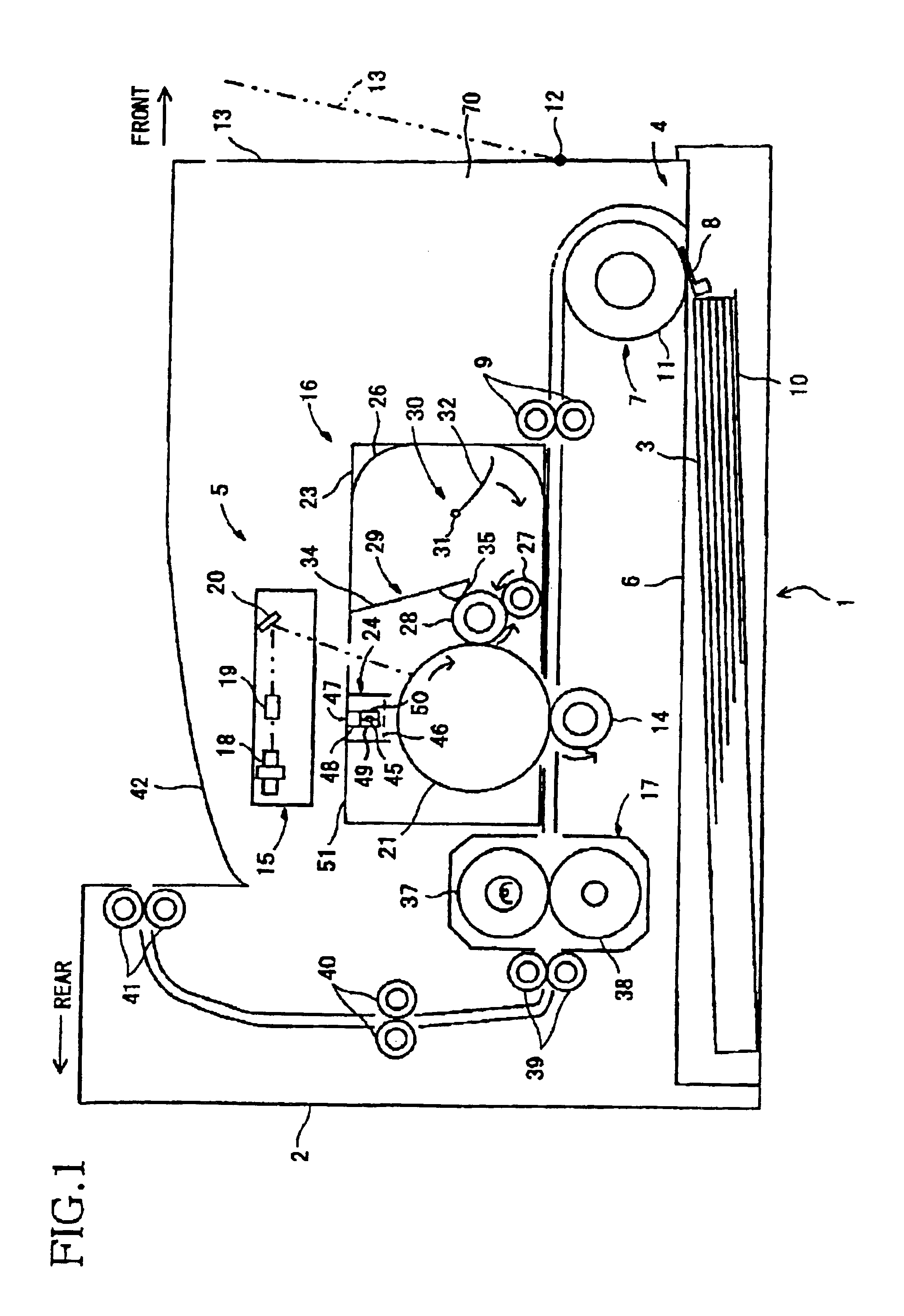
[0019]In FIG. 1, a laser printer 1 is an electrophotographic laser printer where an imaging process is conducted using a monocomponent, non-magnetic development system. A casing 2 includes a feeder unit 4 that supplies sheets 3 into the laser printer 1, and an image forming unit 5 where images are formed on supplied sheets 3. In the following, a side where a paper feed roller 11 is provided is a front side of the laser printer 1, and a side where a fixing unit 17 is provided is a rear side of the laser printer 1.
[0020]The feeder unit 4 is provided at a bottom portion of the casing 2, and includes a sheet feed tray 6, which is detachably attached to the bottom portion of a casing 2, a sheet feed mechanism 7 provided at a front end of the sheet feed tray 6, and resist rollers 9 provided downstream from the sheet feed mechanism 7 in a sheet feed direction.
[0021]The sheet feed tray 6 is of an open-top box shape, and accommodates sheets 3 to be stacked thereon. The sheet feed tray 6 is d...
PUM
 Abstract
Description
Claims
Application Information