
Electromagnetic-signal-time-inversion-based fault point positioning method for transmission line

A transmission line, electromagnetic signal technology, applied to the fault location, using the pulse reflection method to detect faults, detecting faults according to the conductor type, etc., can solve the problem that the effectiveness of fault location depends on the extraction effect of traveling wave head, increase the complexity and cost of the monitoring system, Single-ended measurement method is difficult to apply and other problems, to achieve the effect of speeding up inversion calculation speed, saving calculation costs, and eliminating positioning errors

Active Publication Date: 2018-10-23
XI AN JIAOTONG UNIV
View PDF3 Cites 27 Cited by
  • Summary
  • Abstract
  • Description
  • Claims
  • Application Information

AI Technical Summary

Problems solved by technology

For the multi-terminal distributed power distribution network, there is a complex topology structure of multi-load, multi-fork, and distributed power generation. The single-end measurement method is difficult to apply, and the double-terminal measurement method (or multi-terminal measurement method) needs to carry out the measurement data of each terminal. High-precision time synchronization and remote communication of data, which undoubtedly increases the complexity and cost of the monitoring system
The above method improves the reliability of the traveling wave method to a certain extent, but the effectiveness of fault location still depends heavily on the extraction effect of the traveling wave head

Method used


Image

  • Electromagnetic-signal-time-inversion-based fault point positioning method for transmission line
  • Electromagnetic-signal-time-inversion-based fault point positioning method for transmission line
  • Electromagnetic-signal-time-inversion-based fault point positioning method for transmission line

Examples


Embodiment Construction

[0047] In recent years, Time Reversal (TR), as a new technology based on signal time-domain reverse sequence operation, has the characteristics of dual focus in time and space, and is widely used in acoustics, biomedicine, radar imaging, communication, electromagnetic radiation positioning, etc. Many fields have developed rapidly. Considering the description of a two-conductor line (or a single-conductor line on an ideal earth) in the lossless case, we can describe the wave propagation process by the following telegraph equation

[0048]

[0049]

[0050] Among them, v(x, t) and i(x, t) are the voltage and current on the transmission line, respectively, and L' and C' are the inductance and capacitance per unit length of the transmission line.

[0051] Applying the time-reversal transformation (t→-t) to the above equation, we get

[0052]

[0053]

[0054] Among them, due to the change of the direction of movement of the charge, the current i(t) should be negative ...


PUM


Abstract

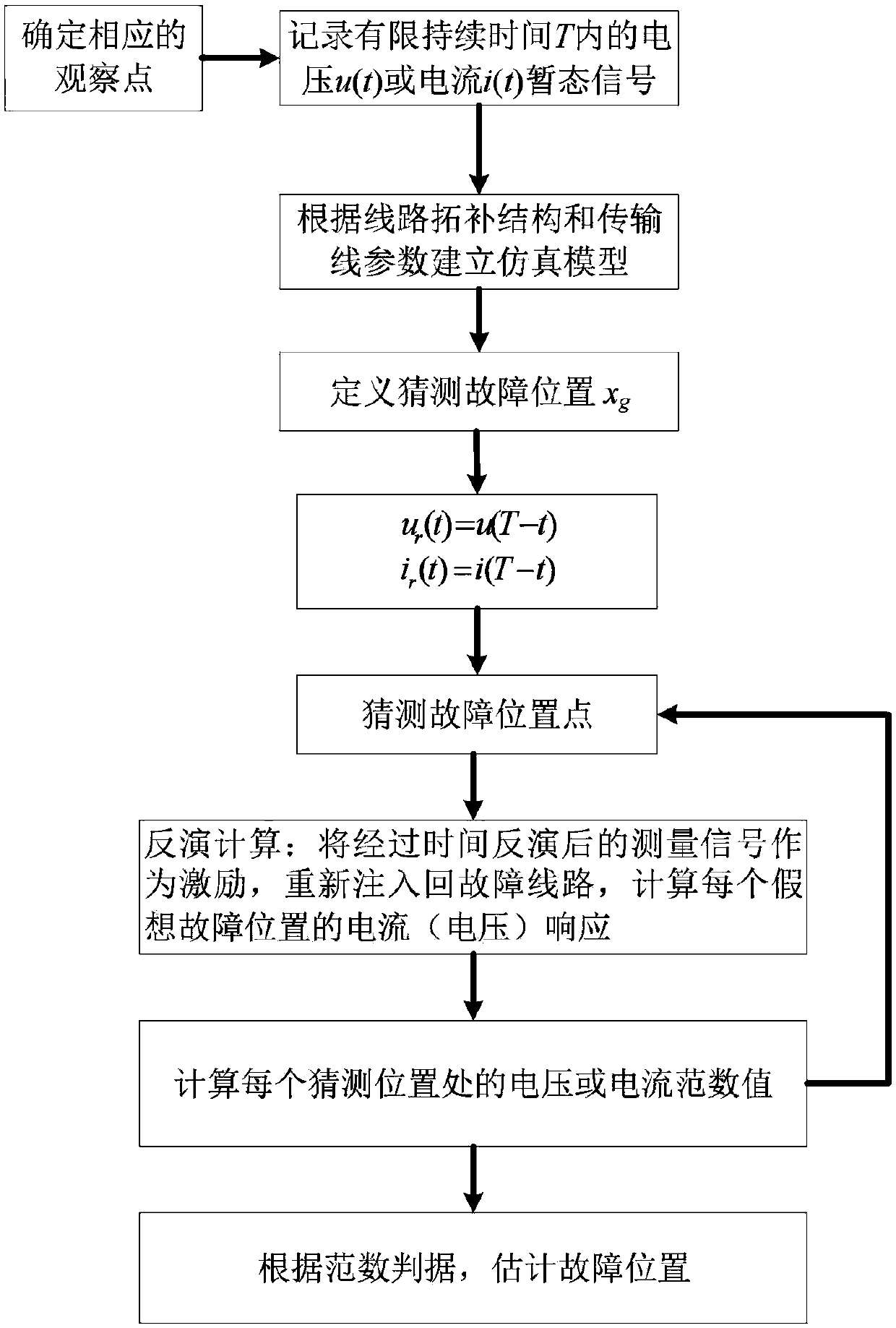
The invention relates to an electromagnetic-signal-time-inversion-based fault point positioning method for a transmission line. On the basis of an electromagnetic time inversion principle, a single observation point is set at any terminal in a power distribution network and a fault high-frequency transient signal within a limited period of time is measured and recorded; and time inverted sequenceprocessing is carried out on the measured signal, the processed signal is injected into a power distribution network simulation calculation model at an observation point, norm values at different guess positions in the power distribution network are calculated, and a fault position is determined by searching for a maximum peak value and a maximum energy root value. According to the method different form the traditional traveling wave determining method and impedance method, a power distribution network with a complex topological structure can be covered by one observation point without being affected by the fault impedance; and the excellent anti-noise performance is realized. The electromagnetic-signal-time-inversion-based fault point positioning method has the great practical value in fault positioning of the transmission line.

Description

technical field [0001] The invention belongs to the fields of power system relay protection and distribution network fault location, and in particular relates to a fault diagnosis and location method based on fault high-frequency transient signal analysis. Background technique [0002] Transmission lines are the basic components of the power grid. Due to the wide distribution and long-term exposure of high-voltage transmission lines to harsh natural environments such as wind, rain, thunder, and electricity, failures will inevitably occur. These faults directly affect the safe and reliable operation of transmission lines, and even cause large-scale power outages in severe cases. Therefore, after a fault occurs, it is very important to check the fault location as soon as possible, deal with the accident, and quickly restore power supply, which is very important for improving the safe operation level and operational reliability of the power system. Finding the fault point afte...

Claims


Application Information

Patent Timeline
Patent Type & Authority Applications(China)
IPC IPC(8): G01R31/08G01R31/11
CPCG01R31/085G01R31/088G01R31/11
Inventor 谢彦召和少寅
Owner XI AN JIAOTONG UNIV
Learn More