Shelf structure

a shelf and structure technology, applied in the field of shelves, can solve the problems of requiring a great amount of time and labor in assembly and disassembly, and achieve the effects of enhancing mechanical stability, enhancing safety, and overall strength

Inactive Publication Date: 2005-07-26
LIN CHI I
View PDF10 Cites 60 Cited by
  • Summary
  • Abstract
  • Description
  • Claims
  • Application Information

AI Technical Summary

Benefits of technology

[0009]To achieve the above objects, in accordance with the present invention, there is provided a shelf comprising upright columns and first and second horizontally extending bars having ends connected to the columns. The column comprises side walls each defining at least one first hole and forming a first rib adjacent the first hole. The first bar is arranged in a first horizontal direction with the end thereof connected to the column. The end of the first bar forms an end tab in which at least one first hook is formed and fit into the first hole of one of the side walls. The first hook has a surface forming a second rib. The second rib receivingly engages the first rib to strength the connection between the end of the first bar and the column. The second bar is arranged in a second horizontal direction with the end thereof connected to the column. The end of the second bar forms an end tab in which at least one second hook is formed and fit into the first hole of another one of the side walls. The second hook has a surface in which a third rib is formed. The third rib receivingly engages the first rib to strength the connection between the end of the second bar and the column. By means of the structure of the columns and bars, the shelf can be efficiently assembled / disassembled and has a structure of enhanced mechanical stability, security, safety and overall strength.

Problems solved by technology

Since tightening and loosening bolts is a time and labor consuming work, the conventional shelf illustrated in FIG. 1, although being disassembleable by the general consumers, requires a great amount of time and labor in doing assembly and disassembly.

Method used


Image

  • Shelf structure
  • Shelf structure
  • Shelf structure

Examples


Embodiment Construction

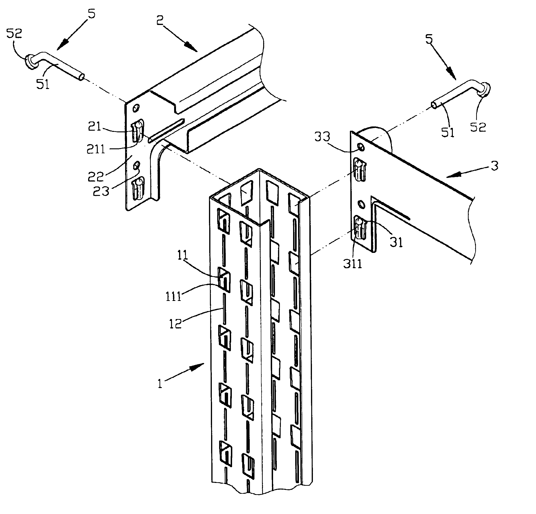
[0017]With reference to the drawings and in particular to FIG. 3, a shelf constructed in accordance with the present invention comprises a number of upright or vertical columns 1 and longitudinal and transverse bars 2, 3 extending in horizontal directions and connected between adjacent columns 1. In the embodiment illustrated, the shelf comprises four columns 1 arranged at four comers of a rectangle and four sets of bars 2, 3 are mounted to and connected with the columns 1 in a spaced manner along the vertical direction whereby four levels are formed in the shelf. Each set of bars comprises two longitudinal bars 2 opposite to each other and each connected between two adjacent columns 1 and two transverse bars 3 opposite to each other and each connected between adjacent columns 1 whereby the longitudinal and transverse bars 2, 3 form a rectangle with the columns 1 located at the comers. However, it is apparent to those having ordinary skills to arrange the columns 1 and the bars 2, 3...


PUM


Abstract

A shelf including upright columns and first and second horizontally-extending bars having ends connected to the columns. The column has side walls each defining at least one first hole and forming a first rib adjacent the first hole. The first bar is arranged in a first horizontal direction with the end connected to the column. The end of the first bar forms an end tab in which at least one first hook is formed and fit into the first hole of one of the side walls. The first hook has a surface forming a second rib. The second rib receivingly engages the first rib to strength the connection between the end of the first bar and the column. The second bar is arranged in a second horizontal direction with the end connected to the column. The end of the second bar forms an end tab in which at least one second hook if formed and fit into the first hole of another one of the side walls. The second hook has a surface in which a third rib is formed. The third rib receivingly engages the first rib to strength the connection between the end of the second bar and the column.

Description

FIELD OF THE INVENTION[0001]The present invention generally relates to a shelf having a disassembleable structure, and in particular to a disassembleable shelf having a sound, secured, high strength and safe structure that can be efficiently assembled and disassembled.BACKGROUND OF THE INVENTION[0002]A conventional disassembleable shelf is comprised of upright columns and horizontal bars connected at both ends to the upright columns. An example of the conventional disassembleable shelf is shown in FIG. 1 of the attached drawings, wherein the shelf comprises upright and horizontal elongate members 6, including upright column and horizontal bar, having an L-shaped cross section, such as angled steel. Holes 7 are defined in the elongate members 6. In assembling the shelf, holes of the horizontal bar are aligned with holes of the upright column for the extension of bolts 7 therethrough. The bolts 7 secure the horizontal bar and the upright columns together to form a sound shelf structur...

Claims


Application Information

Patent Timeline
Patent Type & Authority Patents(United States)
IPC IPC(8): A47B57/40A47B57/00
CPCA47B57/40A47B57/408
Inventor LIN, CHI-I
Owner LIN CHI I
Why Eureka
Try Eureka