Stimulation lead design and method of manufacture

a technology of stimulation lead and manufacturing method, which is applied in the direction of internal electrodes, basic electric elements, therapy, etc., can solve the problems of unusable lead removal, defective or inoperable electrical leads, and increase patient stress, so as to improve electrical conduction stability, increase mechanical stability, and prevent the effect of polymer material migration

Active Publication Date: 2011-06-07
CIRTEC MEDICAL CORP
View PDF18 Cites 77 Cited by
  • Summary
  • Abstract
  • Description
  • Claims
  • Application Information

AI Technical Summary

Benefits of technology

[0014]Incorporated within the wall of the polymer lumen or lead body are coils which have an annular 360° extension within the polymer lumen or lead body. The coils are similar to wires in a spiral orientation. The coils provide a rigid structure to the wall of the polymer lumen or lead body under the electrode ring and conductor wire during the swaging process. In addition to providing improved rigidity to the polymer wall of the lumen, the coils provide pressure points that make physical contact against the conductor wire. This secures the conductor wire in place and retards the possible migration of the lumen polymer due to cold flow.
[0017]In the present invention, however, the conductor wires reside inside the hollow opening of the polymer lead body. Each conductor wire individually traverses through the hollow lumen from the proximal portion to the distal portion. At these opposed end portions the conductor wire is advanced through an opening of the wall of the lead body and secured under a respective electrode ring. The length of that portion of a conductor wire that penetrates or protrudes through the wall of the lead is substantially the same as the length of the electrode ring. That way, the protruding portion of the conductor wire is fit under the electrode and is not exposed to the external environment. Instead, the entire protruding portion of the conductive wire is in contact with the inside surface of the electrode ring. Once the protruding portion of the conductor wire is inserted under the electrode ring, the conductor wire and electrode ring are swaged together, supported on the outer surface of the lead lumen. A series of metallic coils is embedded in the walls of the electrode lead body, one in the area of each electrode ring. The metallic coils provide added mechanical stability to the lead body during the swaging process as well as create a barrier to migration of the polymer material between the electrode ring and the conductor wire. In that respect, this new design provides increased electrical conduction stability through control of polymer migration in a manner that provides a more slender lead design that does not have material use restrictions.

Problems solved by technology

It is undesirable for the lead to be removed once inserted into the patient if; for example, the electrical lead becomes defective or inoperable.
Removing an electrical lead creates additional stress for the patient and increases the risk of infection both when an electrical stimulation lead is removed as well as when a new electrical stimulation lead is implanted.
One such mode of failure in current implantable electrical stimulation leads is impaired electrical contact.
Such a problem can occur due to the cold flow of the polymer as it migrates between the conductor wire and the electrode ring.
This problem is most concerning for chronic or long term implant electrical leads which can reside in a patient over many years.
Over time, the polymer of the electrical lead body can become “sandwiched” between the electrode and the conductor wire, which results in impaired electrical conduction between the electrode ring and conductor wire.
This problem of impaired electrical contact between the conductor wire and lead body is a major concern for chronic or long term electrical stimulation leads.
In such prior art designs, the force of the crimping damages the polymer lead body; therefore requiring metal inserts to serve as a solid rigid protective barrier to the surface and structure of the polymer lead lumen.
Further, the use of a sleeve or core insert in the crimping process adds additional width to the body of the electrical lead which is undesirable because it makes it more difficult for the electrical lead to penetrate deep within narrow passages of the human body.
Welding does not require additional crimping components such as a sleeve or core insert, but limits the use of available materials due to its excessive heat and undesirable material reactions that are inherit in the welding process.
For example, welding will expose silver in silver cored wire, a commonly used material for use as a conductor; the exposed silver dissolves in the body which could result in bodily harm.
Material migration into the body can further result in a weakened bond that increases the probability of a break in the conductor wire, resulting in impaired stimulation lead operation.
If a break occurs, the electrical stimulation lead will need to be replaced; therefore requiring the patient to undergo an additional operation creating more unnecessary trauma and stress to the patient.
As previously mentioned, the problem with current implanted electrical leads is a propensity for the electrical connection between the conductor wire and electrode ring to degrade over time.
The presence of polymer material there can create an interruption in the electrical continuity between the conductor wire and electrode ring, thus impairing the electrical stimulation to the patient.

Method used


Image

  • Stimulation lead design and method of manufacture
  • Stimulation lead design and method of manufacture
  • Stimulation lead design and method of manufacture

Examples


Embodiment Construction

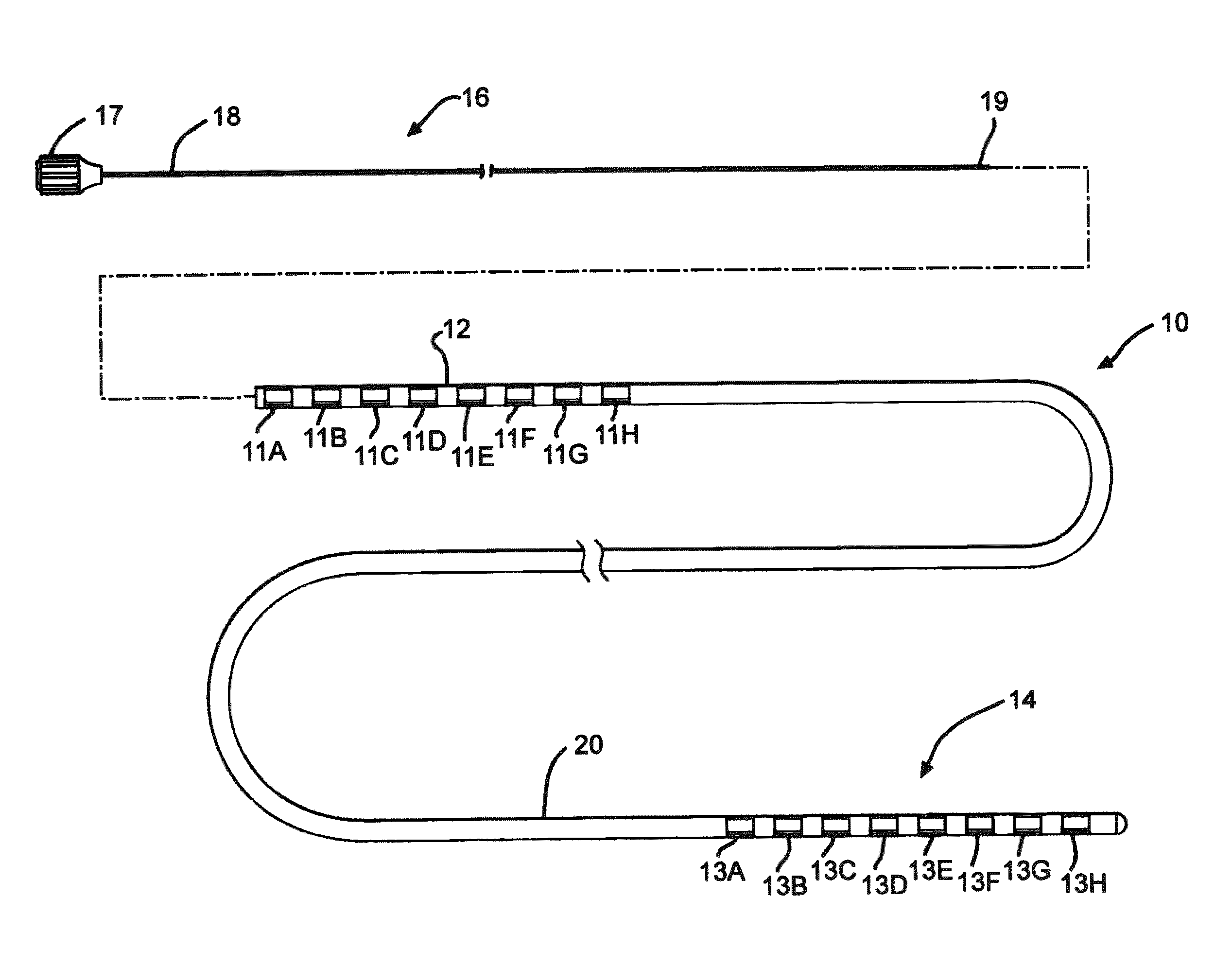
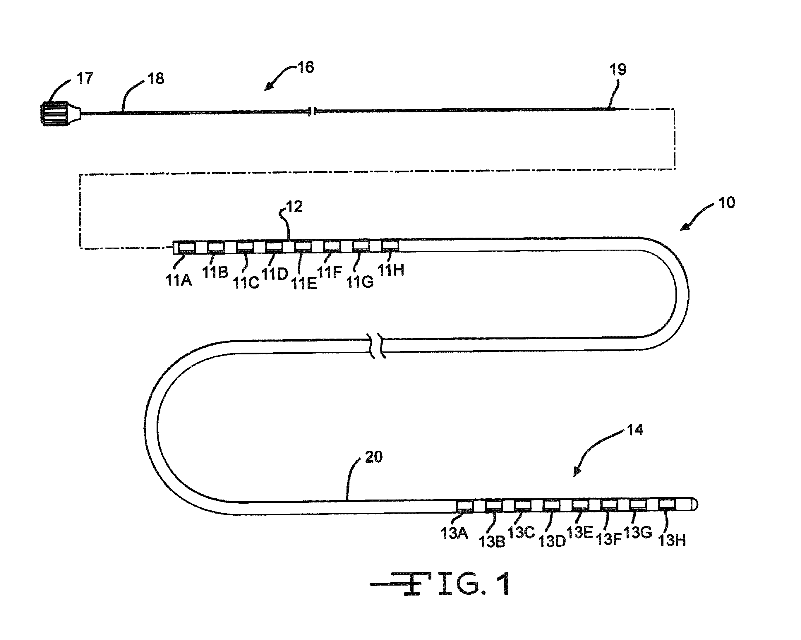
[0029]FIG. 1 illustrates an electrical stimulation lead 10 according to the present invention for delivering therapeutic electrical stimulation. The stimulation lead 10 comprises a proximal portion 12 and a distal portion 14. Within the proximal portion 12 and the distal portion 14, respectively electrode rings 11A-11H and 13A-13H are attached to the outer surface of the polymer lead body 20. The lead body 20 is comprised of polyurethane polymer. The lead body 20 can also be comprised of alternate materials such as silicone, polyethylene, polyimide, PEEK and other biocompatible and biostable polymeric materials.

[0030]Each of the electrode rings 11A-11H and 13A-13H has an annular shape extending 360° around the outside surface of the stimulation lead body 20. Although eight electrode rings are depicted in both proximal portion and distal portions12, 14 of FIG. 1, the number of electrode rings could range from one to as many as about thirty six or more depending on the length of the s...


PUM

PropertyMeasurementUnit
diameteraaaaaaaaaa
diameteraaaaaaaaaa
lengthaaaaaaaaaa

Abstract

The invention is an implantable electrical stimulation lead for chronic or long term use that has an improved electrical connection between the electrode and conductor. This is accomplished through the use of metal coils embedded in the sidewall of the lead body. A wire conductor providing electrical continuity from a proximal electrode to a distal electrode has a protruding portion extending through the sidewall. This protruding portion can reside adjacent to either a proximal or a distal electrode. In any event, the protruding portion of the lire is captured underneath a ring electrode that is physically deformed into direct contact with the metal of the wire, preferably by swaging. This serve to make electrical conductivity between the wire and the electrode with the embedded coil serving as support during the swaging process.

Description

CROSS-REFERENCE TO RELATED APPLICATION[0001]This application claims priority from U.S. Provisional Application Ser. No. 61 / 075,955, filed Jun. 26, 2008.FIELD OF THE INVENTION[0002]The present invention is related generally to implantable medical devices. More specifically, the present invention is related to implantable medical electrical leads.BACKGROUND OF THE INVENTION[0003]Implantable medical devices designed for patient pain management, also known as neuromodulation devices, have improved dramatically over the past few decades. These implantable medical devices provide much needed relief for patients who suffer from pain which emanates from the spine region. One of the key components of such devices is the implantable electrical stimulation lead. Some electrical stimulation leads, also referred to as percutaneous stimulation leads, are implanted into the patient by insertion of the electrical lead through the skin, through the ligamentum flavum, and into the epidural space or e...

Claims


Application Information

Patent Timeline
Patent Type & Authority Patents(United States)
IPC IPC(8): A61N1/00
CPCA61N1/0551A61N1/05Y10T29/49002
Inventor SWOYER, JOHN M.
Owner CIRTEC MEDICAL CORP
Why Eureka
Try Eureka