Valve security device

a security device and valve technology, applied in the direction of valve housings, mechanical control devices, instruments, etc., can solve the problems of disabling the fluid flow valve, and achieve the effect of disabling the valve and being highly versatil

Inactive Publication Date: 2005-07-26
FLOW SECURITY SYST
View PDF6 Cites 9 Cited by
  • Summary
  • Abstract
  • Description
  • Claims
  • Application Information

AI Technical Summary

Benefits of technology

[0003]Briefly, the present invention comprises a fluid flow valve security device that fits about and is secured to the actuating key on a valve head to selectively prevent access thereto and the unauthorized opening of the valve. The security device includes an inner body portion, an outer body portion, a protective sleeve, a valve cap and an operating pin assembly. The inner body portion is disposed about and operatively coupled to the valve actuating key such that rotation of the inner body portion effects corresponding rotation of the key to open and close the valve. The outer body portion of the security device is disposed about and rotatably mounted on the inner body portion. The valve cap is mounted atop the outer body portion for rotational movement therewith and defines a secondary actuating key thereon preferably corresponding in configuration to the actuating key on the valve head. The protective sleeve is secured between and freely rotatable about the interface of the inner and outer body portions and the actuating key on the valve head so as to prevent unauthorized access thereto.
[0004]The security device of the present invention is controlled by an operating pin assembly that is manually movable between an extended position and a retracted position. In its extended position, the pin assembly couples the outer body portion of the security device to the inner body portion thereof such that the secondary actuating key is operatively coupled to the actuating key on the valve head whereby the valve can be opened and closed by the secondary actuating key. If desired, with the operating pin assembly in the extended position the valve cap can be removed from the outer body portion to disassemble and remove the security device from the valve head. In the retracted position, the outer body portion is uncoupled from the inner body portion of the device and the valve cap is coupled to the outer body portion such that the outer body portion and valve cap are free wheeling on and about the inner body portion and the valve cap can not be removed from the outer body portion. Thus, with the operating pin assembly in the retracted position, the security device can not be removed from the valve head and the secondary key on the valve cap is not operatively coupled to the valve head key, totally disabling the fluid flow valve. The protective sleeve is also freely rotatable about the interface of the inner and outer body portions, preventing one from obtaining unauthorized access to said interface or the valve head actuating key in an effort to remove or overpower the security device.
[0005]To prevent unauthorized movement of the operating pin assembly from the retracted position to the extended position to open the valve and to inhibit the unauthorized locking of the valve in the operative mode, a channel is provided in an extended portion of the outer body of the device adjacent the operating pin assembly which, with the assembly in the retracted position, is adapted to receive the shackle of a padlock or tamper-proof lock having an inaccessible shackle, depending on the application. With the shackle extending through the channel, the operating pin assembly is held in the retracted position disabling the valve. With the operating pin assembly in the extended position, the channel is blocked by the pin assembly preventing the insertion of a lock shackle and the disabling of the valve.
[0006]Through the aforesaid configuration, when the valve security device of the present invention is used to secure a valve of the type that might need to be opened in an emergency situation such as a fire hydrant, a conventional padlock could be used to secure the operating pin assembly and a fireman, policeman or other person, in an emergency, could cut or saw through the shackle of the padlock to remove the lock and reestablish control over the valve head. For those applications in which higher security is required, a tamper-proof lock employing, for example, an inaccessible T-shaped shackle could be utilized which would prevent one from overcoming the lock without the key. Thus, the present invention provides a highly versatile locking device for use in a wide variety of applications.

Problems solved by technology

Thus, with the operating pin assembly in the retracted position, the security device can not be removed from the valve head and the secondary key on the valve cap is not operatively coupled to the valve head key, totally disabling the fluid flow valve.

Method used


Image

  • Valve security device
  • Valve security device
  • Valve security device

Examples


Embodiment Construction

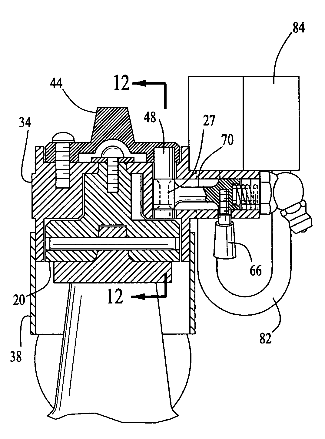
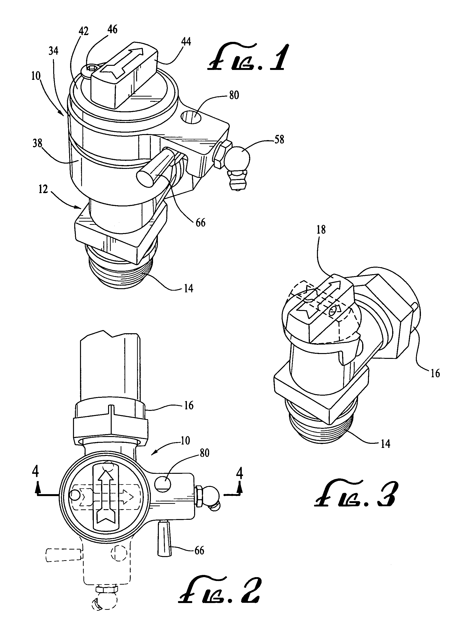
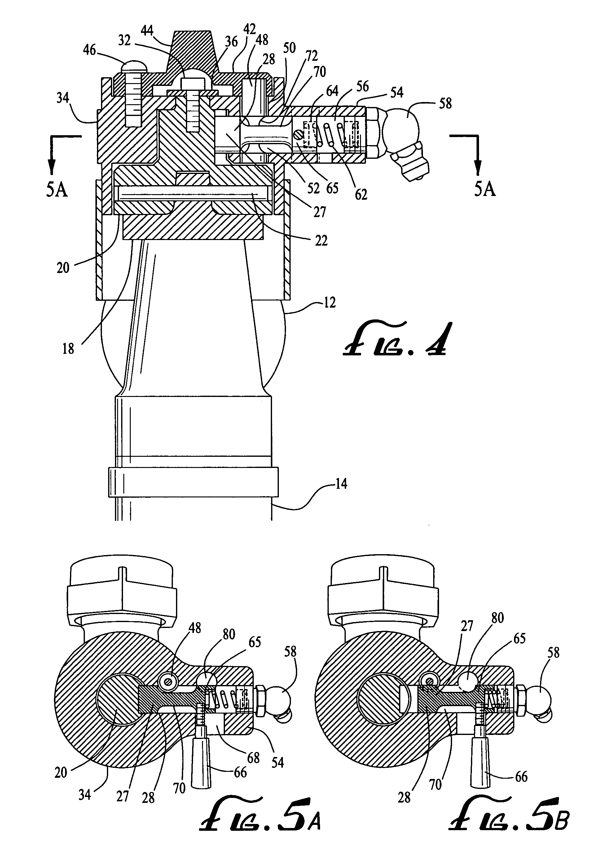
[0020]The valve security device 10 is shown in the accompanying drawings secured to a conventional residential angle stop valve head 12 of the type that is widely used by the Department of Water and Power in the Southern California area and elsewhere. It is to be understood, however, that the security device of the present invention is readily adaptable for use with a variety of fluid flow valves. The valve head 12 includes a water inlet 14, outlet 16 and a key or actuator 18 for actuating the internal valve components (not shown) to regulate the water flow therethrough. The open valve position is illustrated in FIG. 3 in solid lines and the closed position is illustrated in phantom lines.

[0021]The individual components of the valve security device 10 are perhaps best illustrated in the exploded view of FIG. 6. Those components include an inner body 20 which is adapted to fit over and engage the actuator key 18 on the valve head 12. As seen in FIG. 4, the interior of inner body 20 i...


PUM


Abstract

A valve security device for releasably securing a fluid flow valve in an inoperable position including an inner body adapted to be disposed about the valve actuator such that rotation of the inner body effects corresponding rotation of the actuator to open and close the valve and an outer body rotatably mounted about the inner body. A valve cap defining a secondary actuator is mounted on the outer body. An operating pin assembly is carried by the outer body which, in an extended position, operatively couples the outer body to the inner body such that the valve can be controlled by the secondary actuator. In a retracted position, the pin assembly uncouples the outer and inner bodies such that the outer body is freely rotatable on the inner body. A lock secures the operating pin assembly in the retracted position thereby releasably securing the valve in an inoperable position.

Description

BACKGROUND OF THE INVENTION[0001]The present invention relates to valve security devices and, more particularly, to a device that is adaptable for use on a wide variety of fluid flow valves, both liquid and gas, to prevent access to the valve actuating key with varying degrees of security depending on the particular application.[0002]Different levels of security are desirable in valve protection devices depending on the nature of the fluid flow line in which the valve is being used. For example, to provide a security device for a valve on a fire hydrant, it generally would be undesirable to employ a security device that could not be forcibly circumvented with conventional equipment such as a heavy-duty bolt cutter. If such a device was used and the only key that could unlock the device to provide access to the actuating key on the hydrant was lost or temporarily misplaced, firefighters could be prevented from accessing the water in a time of acute emergency. However, some form of lo...

Claims


Application Information

Patent Timeline
Patent Type & Authority Patents(United States)
IPC IPC(8): F16K35/06F16K35/00
CPCF16K35/06Y10T70/5628Y10T70/5637Y10T70/5664Y10T137/7062Y10T137/7256
Inventor NICKEAS, MARKNICKEAS, MARTIN
Owner FLOW SECURITY SYST
Why Eureka
Try Eureka