Hydraulic drive circuit with flow divider and bypass valve

Inactive Publication Date: 2005-08-02
MORGAN GEORGE H
View PDF6 Cites 23 Cited by
  • Summary
  • Abstract
  • Description
  • Claims
  • Application Information

AI Technical Summary

Benefits of technology

[0013]The present invention in the preferred embodiment is a flow divider used in conjuntion with a bypass valve so that a hydraulic drive may be operated either with or

Problems solved by technology

Consequently, applicant is unaware of any successful use of a rotary

Method used


Image

  • Hydraulic drive circuit with flow divider and bypass valve
  • Hydraulic drive circuit with flow divider and bypass valve
  • Hydraulic drive circuit with flow divider and bypass valve

Examples


Embodiment Construction

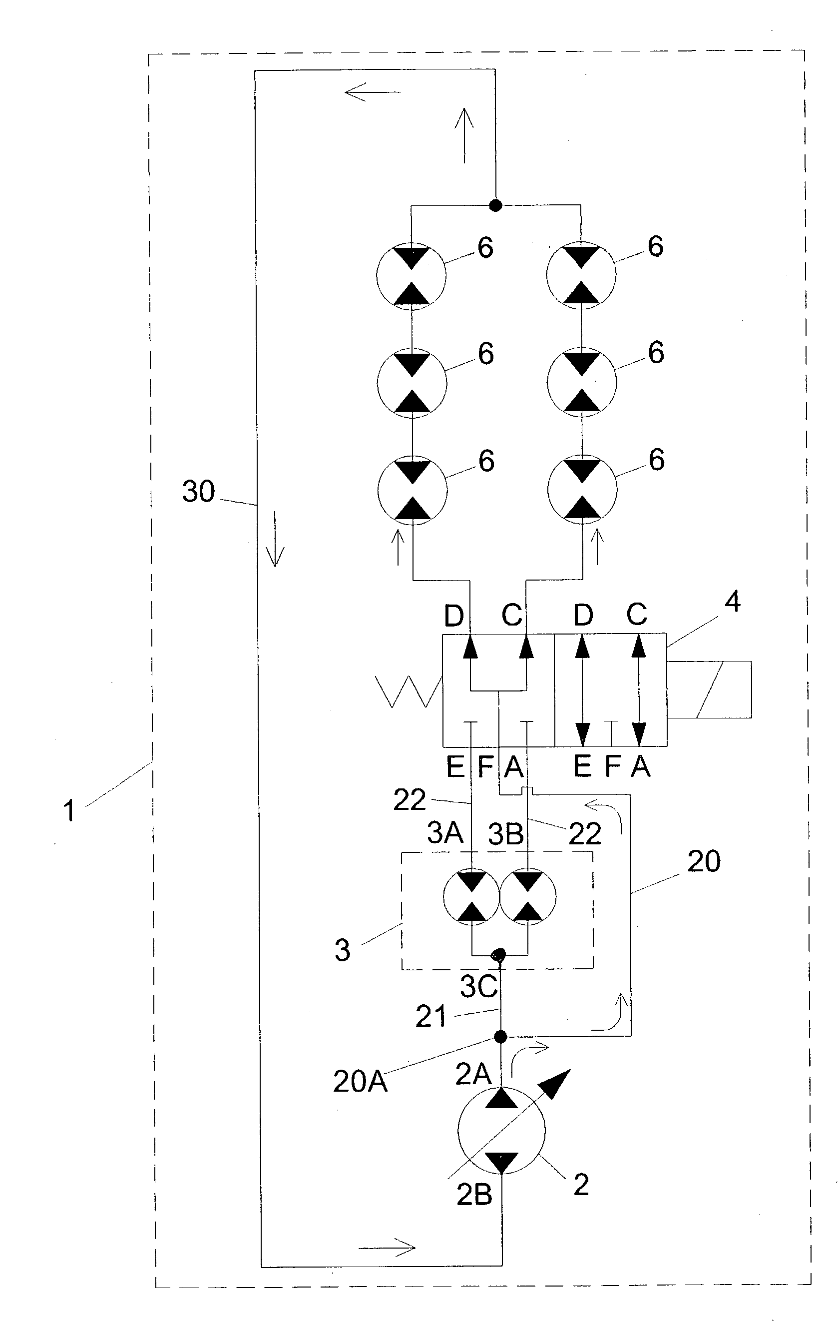
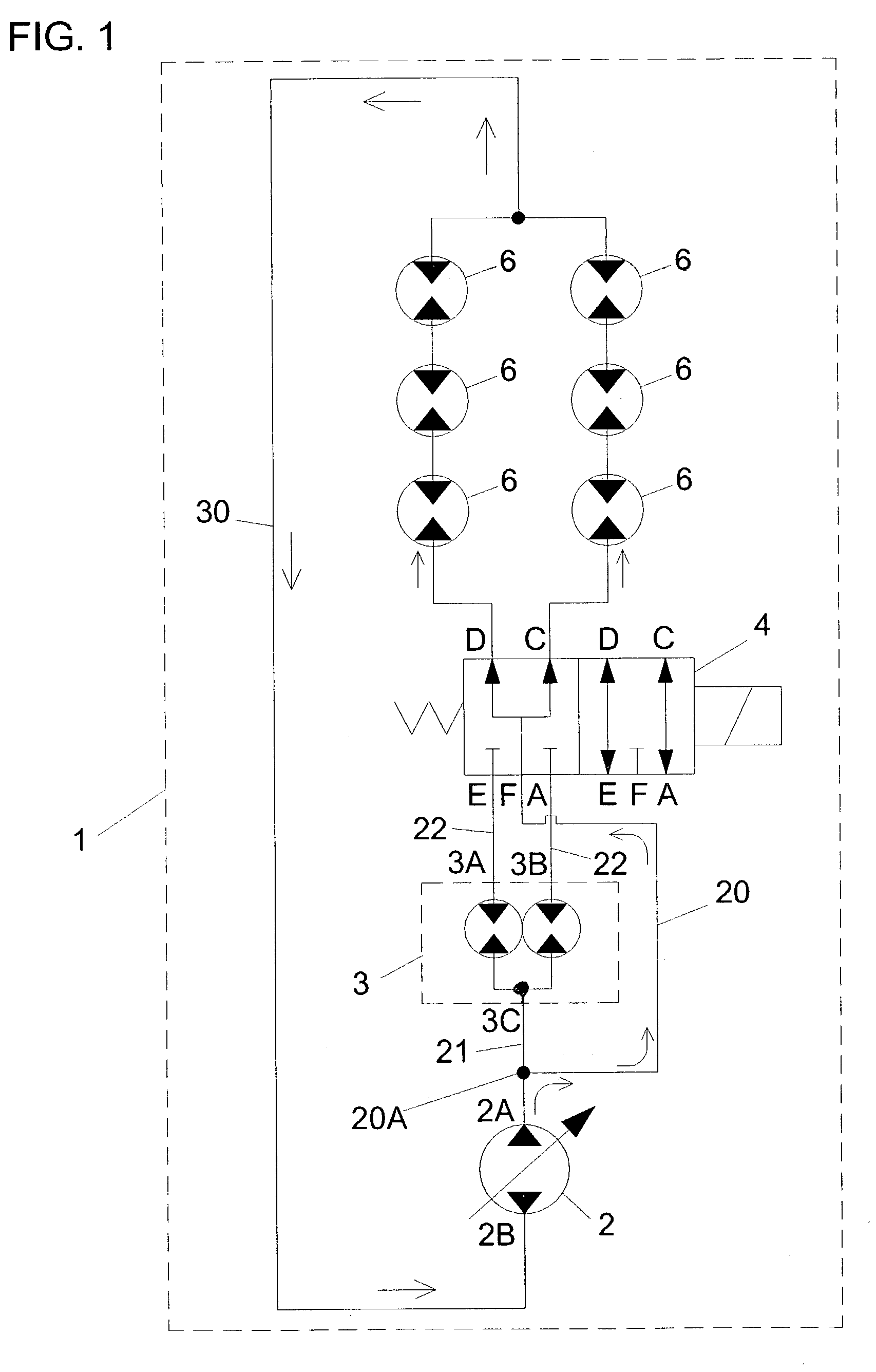
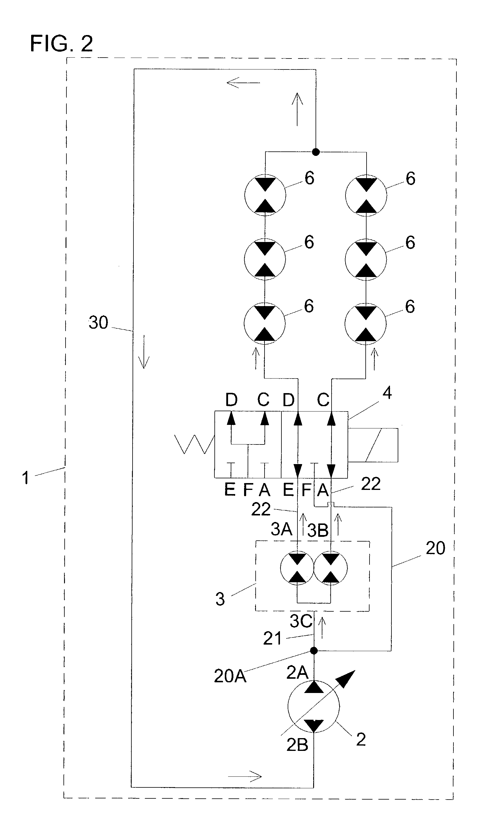
[0016]FIGS. 1 and 2 illustrate the preferred embodiment of the present invention, a hydraulic drive circuit 1 comprising a flow divider 3 and a bypass means 4.

[0017]The circuit 1 further comprises a pump 2, actuators 6, a junction 2A, pressure lines 20, 21, and 22, and return lines 30.

[0018]The pump 2 comprises ports 2A and 2B.

[0019]In the preferred embodiment, the flow divider 3 is a gerotor flow divider, such as is available from White Hydraulics, a manufacturer, located in Hopkinsville, Ky. For enablement purposes, for a 40 gallon per minute pump, the White model FD00181800F is an appropriate model.

[0020]The flow divider 3 comprises output ports 3A and 3B and an inlet port 3C.

[0021]The bypass means 4, in the preferred embodiment, as an enablement disclosure, is a two position, two section, five port valve, with a spring return, known as an SDS selector valve, available from Cross Manufacturing Company, 100 Factory Street, Lewis, Kans. 67552, according to their literature, VSD1 8 / ...


PUM


Abstract

A hydraulic drive with a flow divider and a bypass wherein fluid can either be allowed to flow from a flow divider to hydraulic actuators in parallel or the fluid can be allowed to bypass the flow divider and flow directly to the hydraulic actuators in parallel.

Description

CROSS REFERENCES TO RELATED APPLICATIONS[0001]Provisional Application for Patent No. 60 / 413,402, filed on Sep. 24, 2002, with the same title, “Hydraulic Drive Circuit With Flow Divider and Bypass valve” which is hereby incorporated by reference. Applicant claims priority pursuant to 35 U.S.C. Par. 119(e)(i).STATEMENT AS TO RIGHTS TO INVENTIONS MADE UNDER FEDERALLY SPONSORED RESEARCH AND DEVELOPMENT[0002]Not applicableBACKGROUND OF THE INVENTION[0003]1. Field of the Invention[0004]This invention relates to a hydraulic circuit using a flow divider as a means of dividing flow in conjunction with a valve means that permits bypassing the flow divider as desired.[0005]2. Background Information[0006]Hydraulic systems are popular in applications involving hazardous, dirty, and nasty environments, such as coal mines, quarries, food processing plants, and construction sites. Much effort has been expended in trying to increase the efficiency and performance ranges of hydraulic drives.[0007]Ope...

Claims


Application Information

Patent Timeline
IPC IPC(8): F16D31/02F15B11/22F15B13/02
CPCF15B11/22F15B13/022
Inventor MORGAN, GEORGE H.
Owner MORGAN GEORGE H
Why Eureka
Try Eureka