
Alternate path auger screen

a technology of auger screen and alternative path, which is applied in the direction of drilling pipe, drilling casing, and borehole/well accessories, etc., can solve the problems of delivering the screen into long horizontal runs, causing gaps, and forming bridges of gravel, and achieves the effect of better distribution of gravel

Inactive Publication Date: 2005-08-02
BAKER HUGHES INC
View PDF52 Cites 41 Cited by
  • Summary
  • Abstract
  • Description
  • Claims
  • Application Information

AI Technical Summary

Benefits of technology

[0009]A gravel pack screen assembly has one or more hollow flight augers that a continuous or segmented with multiple upwardly oriented gravel entrances and multiple downwardly oriented gravel exits. The gravel passes through the auger and around any bridge. The auger helps advance the screen into position as well as to centralize it during gravel deposition. The auger protects the screen during run in as well as the internal passages that pass through it due to its structural rigidity. An alternative embodiment features spirally wound tubes with staggered exit locations for better distribution of the gravel.

Problems solved by technology

A common problem when gravel packing is that the gravel forms bridges and leaves gaping areas uncovered as the gravel that is subsequently delivered piles up behind the bridge or blockage.
Another problem is the difficulty in delivering screen into long horizontal runs because of the limited weight available to advance the screen and the possibility that it may simply buckle in the wellbore and cease to further advance.
Yet another issue is the need to centralize the screen as the gravel is delivered for deposition all around it.
Another concern is damage to the screen assembly during run in.
Gravel screens have been provided in the past with surrounding shrouds but the delivery to the desired location could still cause damage to the shroud and the underlying screen.
Annular bridge formation can be aggravated by zones of low flow rates leading to deposition of undue amounts of gravel in concentrations in undesirable locations leading to a bridge ultimately forming.

Method used


Image

  • Alternate path auger screen
  • Alternate path auger screen
  • Alternate path auger screen

Examples


Embodiment Construction

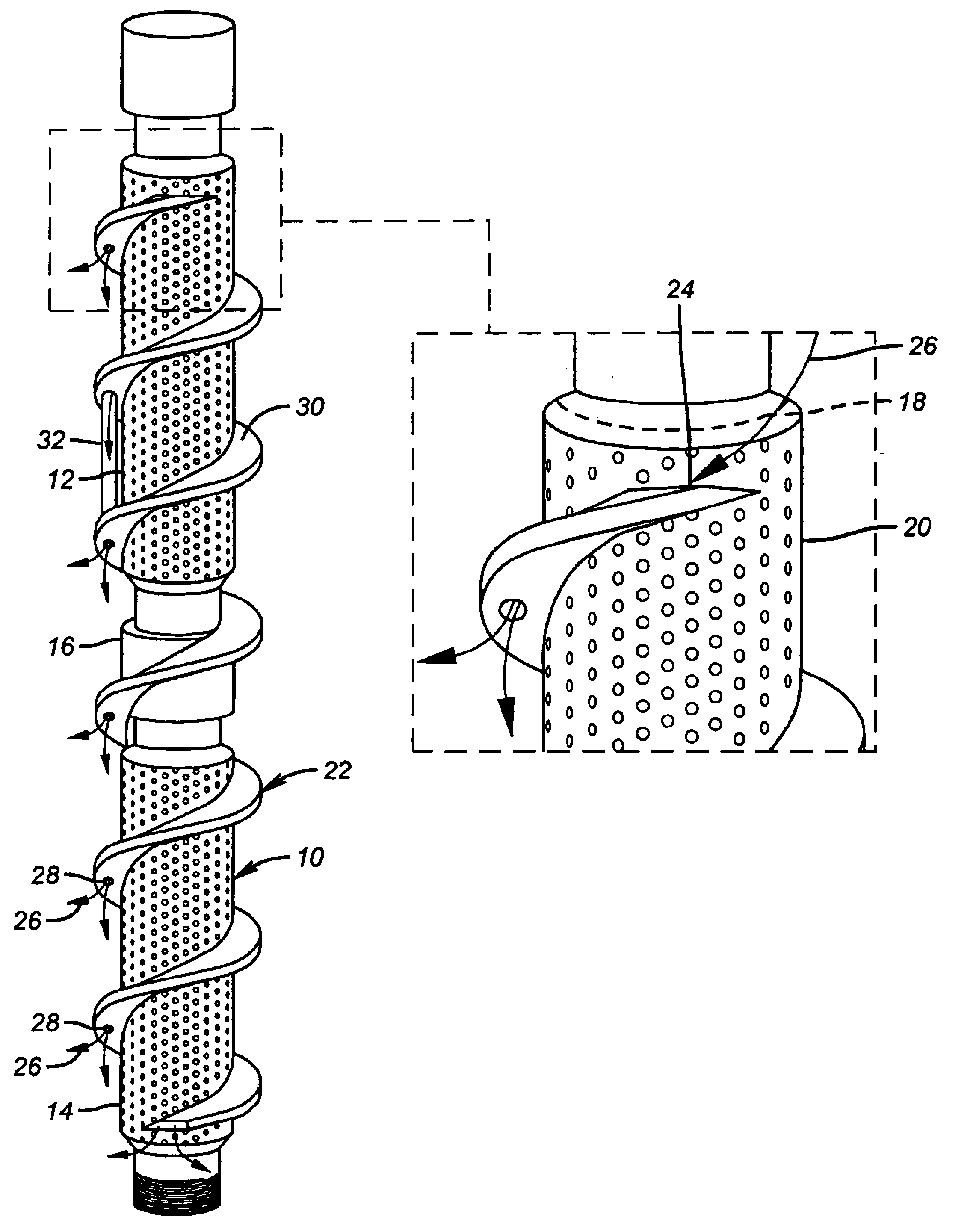
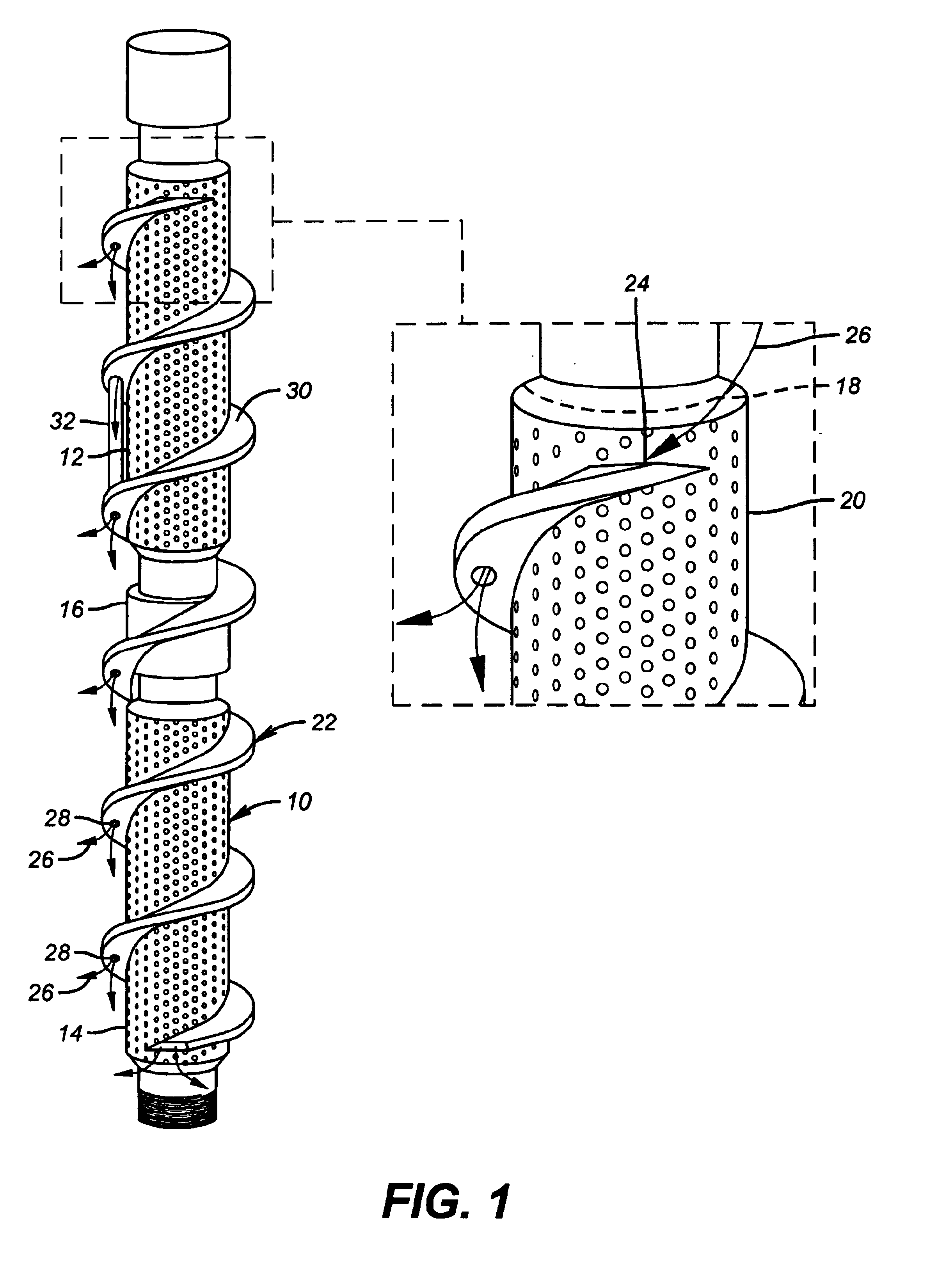
[0015]Referring to FIG. 1 the screen assembly 10 can be made up of multiple sections such as 12 and 14 that are connected by a coupling 16. The actual screen, shown by dashed line 18 is below an outer protective jacket 20. The protective jacket 20 stops short of each coupling 16 so that the proper length of the assembly 10 can be put together for a given application. The auger 22 is hollow and has an inlet 24 near the top where gravel, represented by arrow 26 can enter. There is a plurality of exits 28 on the auger underside for the gravel 26 to exit. The auger 22 may be made continuous over the couplings 16 such as by installing the segments that pass the coupling 16 after it is assembled. Alternatively, the auger 22 can stop before some or all of the couplings 16 and resume on the protective jacket 20 immediately below the coupling 16. In this manner there can be multiple inlets 24 where each section of auger 22 begins. Additionally or alternatively, there can be additional inlets...


PUM


Abstract

A gravel pack screen assembly has one or more hollow flight augers that a continuous or segmented with multiple upwardly oriented gravel entrances and multiple downwardly oriented gravel exits. The gravel passes through the auger and around any bridge. The auger helps advance the screen into position as well as to centralize it during gravel deposition. The auger protects the screen during run in as well as the internal passages that pass through it due to its structural rigidity. An alternative embodiment features spirally wound tubes with staggered exit locations for better distribution of the gravel.

Description

PRIORITY INFORMATION[0001]This application claims the benefit of U.S. Provisional Application No. 60 / 424,401, filed on Nov. 7, 2002.FIELD OF THE INVENTION[0002]The field of this invention relates to alternate paths for gravel during downhole gravel packing operations and more particularly to spirally shaped paths in the form of a surrounding hollow auger for a gravel pack screen assembly. Spirally wrapped shunt tubes are further contemplated.BACKGROUND OF THE INVENTION[0003]A common problem when gravel packing is that the gravel forms bridges and leaves gaping areas uncovered as the gravel that is subsequently delivered piles up behind the bridge or blockage. Another problem is the difficulty in delivering screen into long horizontal runs because of the limited weight available to advance the screen and the possibility that it may simply buckle in the wellbore and cease to further advance. Yet another issue is the need to centralize the screen as the gravel is delivered for depositi...

Claims


Application Information

Patent Timeline
IPC IPC(8): E21B17/00E21B17/22E21B43/02E21B43/08
CPCE21B17/22E21B43/08
Inventor BROOME, JOHN T.NAQUIN, MICHAEL J.
Owner BAKER HUGHES INC
Learn More