
Fixing tool

a technology of fixing tool and fixing rod, which is applied in the direction of snap fasteners, buckles, machine supports, etc., can solve the problems of fixing tool undesirably dropping from the board, and the fixing tool of this reference is not necessarily satisfactory in terms of removal prevention, so as to prevent the tool from dropping from the board. , to achieve the effect of easily mounting and disengaging from the board

Inactive Publication Date: 2005-08-02
TAKEUCHI KOUGIYOU KK
View PDF12 Cites 62 Cited by
  • Summary
  • Abstract
  • Description
  • Claims
  • Application Information

AI Technical Summary

Benefits of technology

[0005]It is an object of the present invention to provide a fixing tool which can be mounted to and disengaged from a board easily and which is prevented from undesirably removing from the board.

Problems solved by technology

If the fixing tool is fitted merely by utilizing its elastic force, when an external force larger than the elastic force is applied to it, the fixing tool may undesirably drop from the board.
Therefore, the fixing tool of this reference is not necessarily satisfactory in terms of removal prevention.

Method used


Image

  • Fixing tool
  • Fixing tool
  • Fixing tool

Examples


Embodiment Construction

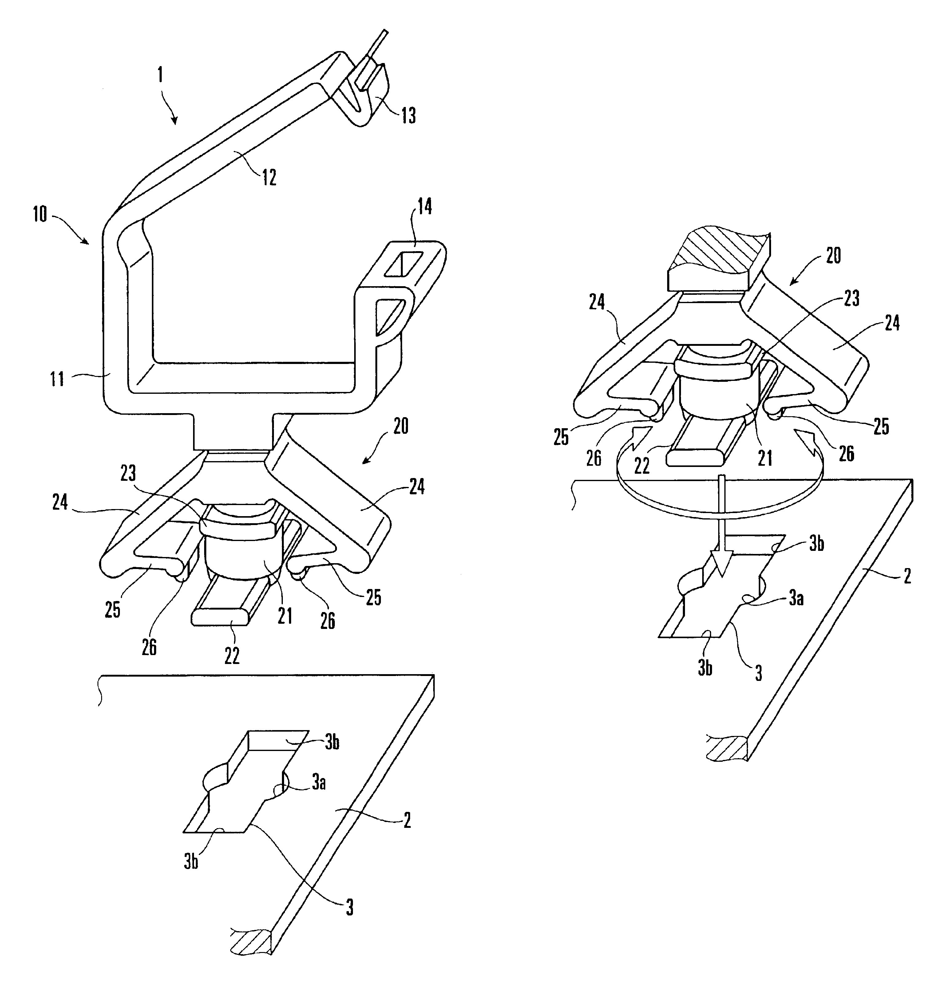
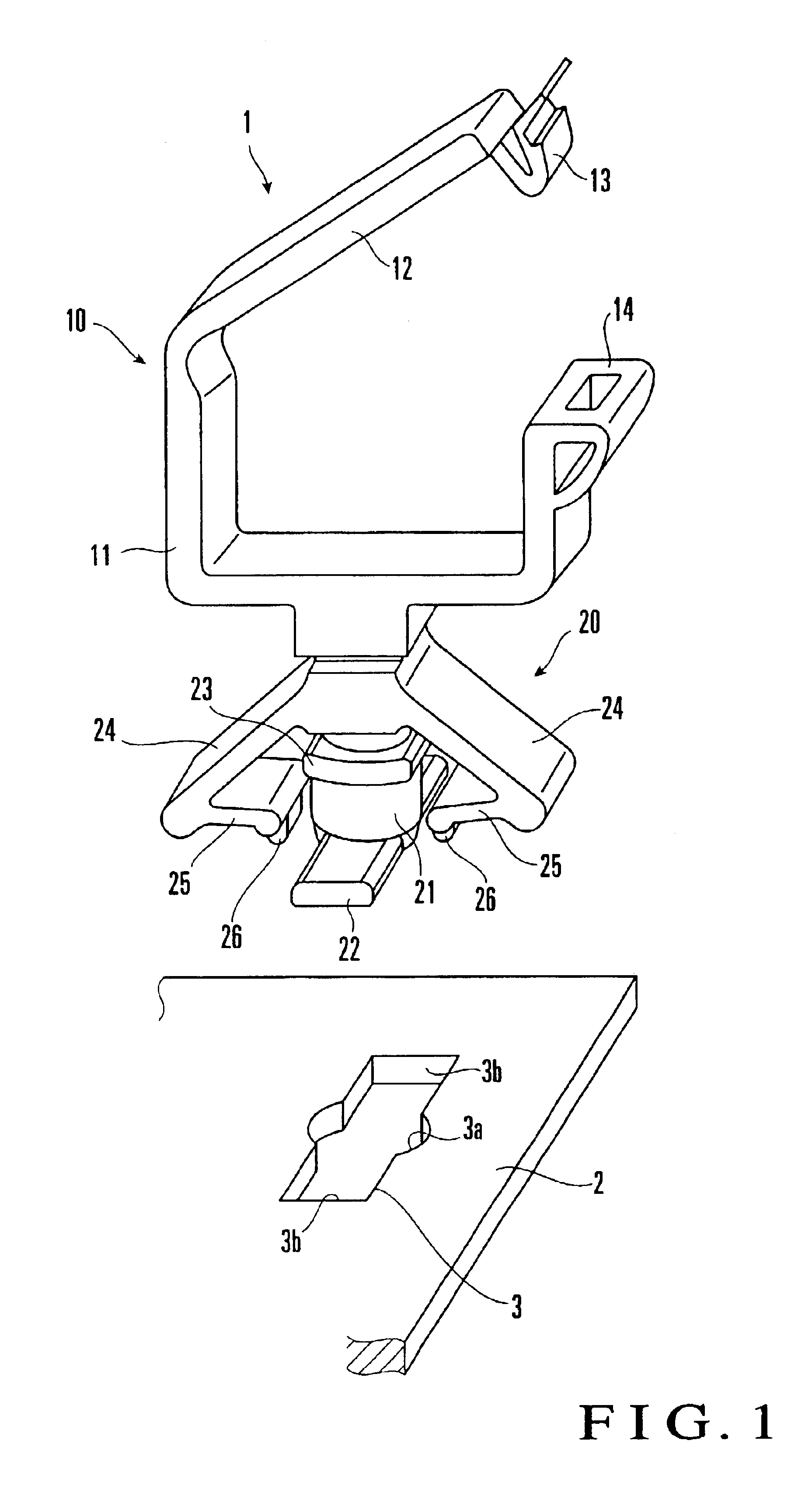
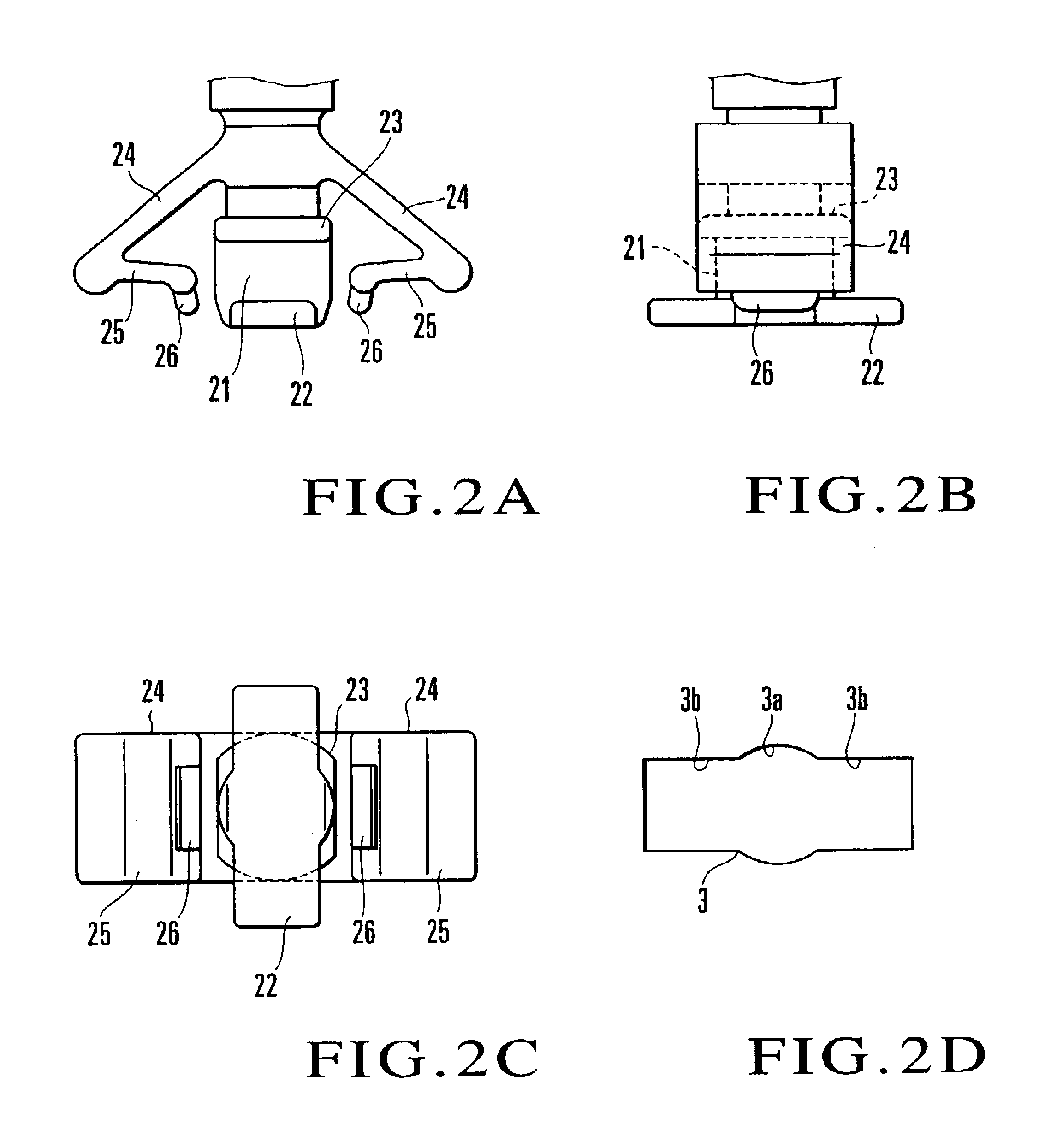
[0024]The embodiments of the present invention will be described with reference to the accompanying drawings. FIG. 1 shows the first embodiment in which a fixing tool according to the present invention is applied to a locking wire saddle type cable clamp (to be merely referred to as cable clamp hereinafter). A cable clamp 1 is comprised of a clamp portion 10 for holding a plurality of cables C in a bundle, and a fixing portion 20 integral with the clamp portion 10 and to be fitted in a mounting hole 3 formed in a board 2. The cable clamp 1 is formed integrally by resin molding or the like. In the clamp portion 10, a cover piece 12 is connected to an upward U-shaped base 11 at its one end through a hinge, and an almost U-shaped locking piece 13 formed at the other end of the cover piece 12 is fitted in a locking portion 14 formed at the other end of the base 11, so that the locking piece 13 is locked by the locking portion 14. The cables (not shown) are inserted in a rectangular ring...


PUM


Abstract

A fixing tool fixes and supports an electronic component on a board, and includes a fixing portion to be mounted on the board. The fixing portion has a post, an engaging piece formed at a distal end of the post and extending in a direction perpendicular to a projecting direction of the post, a wing piece extending from a proximal end of the post in two outward directions perpendicular to the projecting direction of the post, and an engaging projecting portion formed to project at a distal end portion of the wing piece. The engaging piece is inserted in a mounting hole formed in the board and abuts against a lower surface of the board when being rotated along an upper surface of the board. The wing piece abuts against the upper surface of the board to clamp the board together with the engaging piece. The engaging projecting portion is fitted in the mounting hole, when being located at a rotational position, to lock rotation of the fixing portion.

Description

BACKGROUND OF THE INVENTION[0001]The present invention relates to a fixing tool used to mount an electronic component, a cable, or the like on a board for an electronic device or the like and, more particularly, to a fixing tool which performs fixing by utilizing a mounting hole formed in the board.[0002]When assembling an electronic device, electronic components must be mounted on an assembly board such as a panel, chassis, board, or the like (which will be referred to as a board hereinafter), and an interconnecting component such as a cable must be extended on the board. A fixing tool is used for this purpose. In recent years, regarding home electrical appliances, OA devices, automobiles, and electronic devices as a whole, marketing of products that are friendly to the environment is obliged as a solution to the environmental issues. Along with this demand, the fixing tool must be able to be disassembled from the board. Particularly, to facilitate the disassembling operation, the ...

Claims


Application Information

Patent Timeline
IPC IPC(8): F16B21/00F16B21/02H02G3/32H02G3/30H05K7/12F16B21/04
CPCF16B21/02H05K7/12H02G3/32Y10T24/44026
Inventor TAKEUCHI, YASUICHI
Owner TAKEUCHI KOUGIYOU KK
Learn More