Contractible table leg structure

a table leg and contractible technology, applied in the field of table legs, can solve the problems of not providing an effective fixing function and foregoing traditional contractible, and achieve the effects of improving structural strength, manufacturing process, and enhancing structural strength

Inactive Publication Date: 2005-08-02
CHANG CHIEN KUO
View PDF11 Cites 14 Cited by
  • Summary
  • Abstract
  • Description
  • Claims
  • Application Information

AI Technical Summary

Benefits of technology

[0006]The primary objective of the present invention is to provide a contractible table leg structure to solve the problem of the insufficient stability and positioning of the internal and external sleeves of the contractible table leg as described in the foregoing background. A folding rod with deformation stress of the present invention is used to replace the internal sleeve with substantial oval cross section as described in the foregoing background. When the folding rod is secured by a bolt member, the folding rod will produce a deformation stress, such that the folding rod can be pressed tightly inside the inner wall of the sleeve. The positioning ability in the axial direction and the transversal direction of the folding rod can enhance the prior art.
[0007]Another objective of the present invention is to provide a contractible table leg structure, which comprises a folding rod with deformation stress to compensate the discrepancy of the gap from the external sleeve, such that the manufacturing precision will not become a difficulty or a bottleneck of the manufacturing process.
[0008]A further objective of the present invention is to provide a contractible table leg structure, which comprises a folding rod with successive V-shaped folding surfaces. The present invention has a manufacturing process much simpler than the prior-art internal sleeve with oval cross section and an enhanced structural strength.

Problems solved by technology

However, the foregoing traditional contractible table leg has the following problems:
Since the internal and external sleeves have smooth surfaces without sufficient friction, there is still a possibility for the internal sleeve to slide downward due to external forces or actions or the weight of any object on the tabletop, and thus not sufficiently providing an effective fixing function.

Method used


Image

  • Contractible table leg structure
  • Contractible table leg structure
  • Contractible table leg structure

Examples


Embodiment Construction

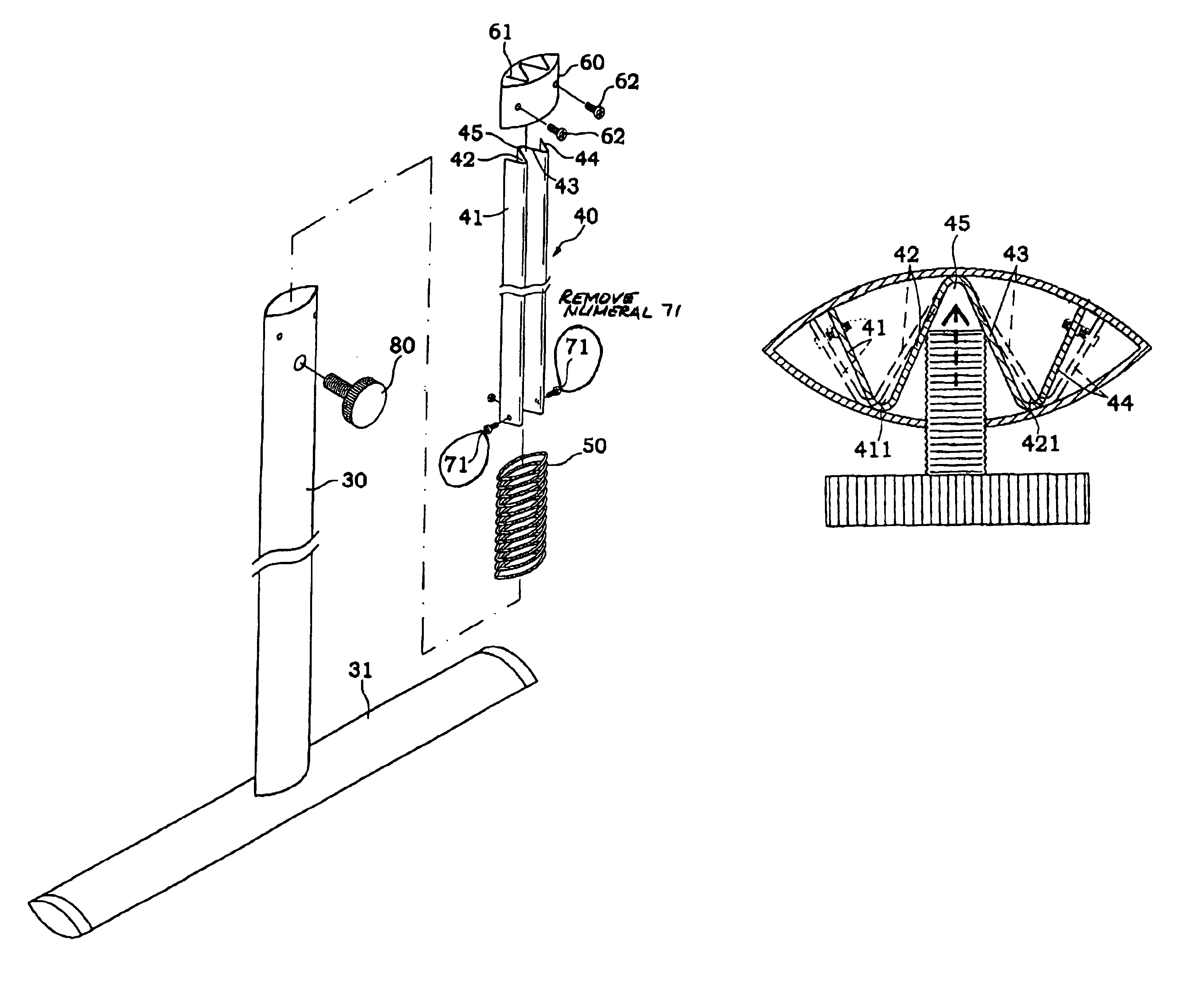
[0016]Please refer to FIG. 3 for the contractible table leg structure of the present invention, which comprises:

[0017]an external sleeve 30, being a pipe member with an oval cross section, and having a stand 31 coupled to its end for standing firmly on the floor;

[0018]a folding rod 40, as shown in FIGS. 3 and 4, being a rod member with a cross-section substantially in successive V-shaped folding surfaces, and this embodiment adopting at least 4 turnings 41, 42, 43, 44, wherein the middle two turnings 42, 43 defining an included angle 45 for the bolt, and the folding rod 40 passing through the external sleeve 30, and its top being coupled to a table top 400;

[0019]a spring 50, as shown in FIGS. 3 and 4, being disposed at the bottom inside the external sleeve 30 and supporting the bottom of the folding rod 40;

[0020]a positioning decorative sleeve, as shown in FIGS. 3 and 4, being a hollow sleeve with an oval cross section, and sleeved at the top of the external sleeve 30, and the top o...


PUM


Abstract

The present invention discloses a contractible table leg structure, comprising: an external sleeve; a folding rod, being a rod member with a cross section substantially in successive V-shaped turning surfaces, and having an included angle in the middle, a plurality of folding surfaces to define a plurality of interface corners, and the folding rod passing through the interior of the external sleeve; a bolt member, being secured on the external sleeve, and its inner end corresponding to the included angle of the folding rod; and when bold the bolt member being tightly secured, so that the folding rod produces a deformation stress to press the interface corner against the inner wall of the external sleeve and fix the position of the folding rod.

Description

BACKGROUND OF THE INVENTION[0001]1. Field of the Invention[0002]The present invention relates to a table leg, more particularly to a contractible table leg capable of adjusting the height of a table to different levels.[0003]2. Description of the Related Art[0004]In general, a traditional contractible table leg structure as shown in FIG. 1 generally includes an external sleeve and an internal sleeve, and the leg coupled to the end of the external sleeve securely standing on the floor, and the internal sleeve precisely passing through the interior of the external sleeve with the top end connecting with the tabletop (not shown in the figure). The internal sleeve can axially move inside the external sleeve to adjust the height of the tabletop. An adjustable bolt is disposed on the external sleeve proximate the top of the external sleeve and tightening the adjustable bolt can press itself against the surface of the internal sleeve to secure the internal sleeve and set the tabletop to a ...

Claims


Application Information

Patent Timeline
Patent Type & Authority Patents(United States)
IPC IPC(8): A47B95/00A47B95/04A47B9/08
CPCA47B9/083A47B95/043
Inventor CHANG, CHIEN-KUO
Owner CHANG CHIEN KUO
Why Eureka
Try Eureka