
System and method for image-based rendering with proxy surface animation

a surface animation and image-based technology, applied in the field of computer graphics including animation, can solve the problems of increasing the number of calculations and other processing work required to fully render the object, affecting the rendering quality of objects, so as to achieve the effect of avoiding burdensome graphics processing and hardware requirements and achieving the immediate level of rendering quality

Inactive Publication Date: 2005-08-02
MORGAN STANLEY +1
View PDF2 Cites 4 Cited by
  • Summary
  • Abstract
  • Description
  • Claims
  • Application Information

AI Technical Summary

Benefits of technology

[0010]Methods and systems for animating proxy surfaces of parts and / or joints of an object are provided. The present invention overcomes each of the above-identified problems and has additional advantages as described herein. An improved animation solution is provided in which a single, relatively small set of view textures is precomputed and during the rendering these textures are mapped on a proxy surface, a simplified version of the complex object. The animation is achieved by animating the proxy surface itself and selecting the appropriate view textures for each animated part. This provides an efficient approach to real-time rendering of complex objects that are animated. In this way, the present invention leverages the formation of object proxies to provide an intermediate level of rendering quality. This intermediate level of rendering quality is then leveraged to produce realistic animation at real-time interactive rates while avoiding burdensome graphics processing and hardware requirements.

Problems solved by technology

These demands include realism, speed and cost.
Complex objects, however, can involve a large number of primitives.
This increases the number of calculations and other processing work required to fully render the object.
In such a billboard approach object data is rendered as if it were mapped or tiled on a flat plane or “billboard.” The billboard approach, however, sacrifices realism and geometry detail.
Accordingly, its usefulness is limited to objects viewed from afar unless hundreds of pre-computed texture images are used exceeding the limits of texture hardware.
Further, using billboards for an animated object is unreasonable because each frame of the animation would require all the view textures needed for a static object.
Not only this would result in a extremely large number of textures that would need to be stored but also would require the animation sequence to be known at the preprocessing step.
Others have been using a single view direction, reducing the number of textures, but making it impossible to view the object from more than a single view direction.
Conventional approaches to forming an object proxy, however, have been limited.
The progressive hull approach described in the Buehler and Sander articles has significant deficiencies.
This progressive hull approach cannot handle concave proxies, or objects that have parts close to each other or touching each other.
In addition, this approach is not well suited for mixing image-based rendering (ibr) objects with regular scenes.

Method used


Image

  • System and method for image-based rendering with proxy surface animation
  • System and method for image-based rendering with proxy surface animation
  • System and method for image-based rendering with proxy surface animation

Examples


example method embodiments

OF THE PRESENT INVENTION

[0061]FIGS. 3A and 3B illustrate a flowchart of a method for image based rendering with proxy surface animation according to an embodiment of the invention. The method includes a preprocessing stage 300A, illustrated by the flow chart of FIG. 3A, and an animation stage 300B, illustrated by the flow chart of FIG. 3B.

[0062]In an embodiment, preprocessing stage 300A operates as follows. An object to be animated is divided into parts. Parts can be generally defined as portions of an object of interest that can move independently with respect to the object without changing shape. Next, a proxy surface is formed for each part. For each proxy surface, a set of view textures is obtained. The method then proceeds to the animation stage 300B. As illustrated in FIG. 3A, method 300 comprises steps 305, 310 and 315. Each of these steps will now be described in further detail with reference to the flowchart of FIG. 3A and an example object in FIGS. 4A-4B.

[0063]In step 305,...

example system embodiment

OF THE PRESENT INVENTION

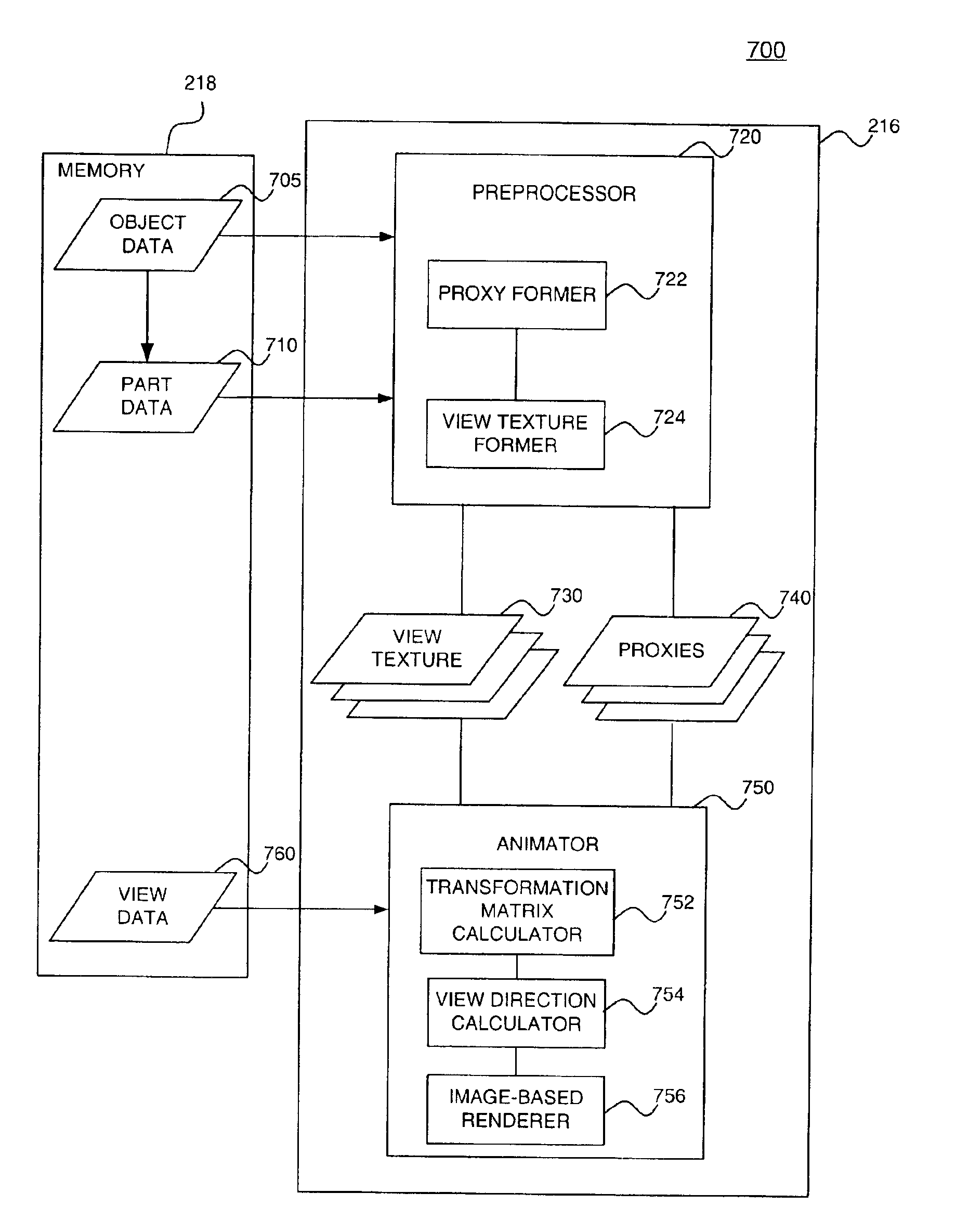
[0082]FIG. 7 shows a graphics system 700 for carrying out methods 300 and 500 according to the present invention. System 700 includes a memory 718, a preprocessor 720 and an animator 750. Preprocessor 720 and an animator 750 both reside in or are executed by processor 716 of a host system (not shown). Processor 716 is communicatively coupled to memory 718, which also resides in the host system. Memory 718 includes object data 705, part data 710, and view data 760.

[0083]Preprocessor 720 includes a proxy former 722 and a view texture former 724. View textures 730 and proxies 740 are passed to animator 750. Animator 750 includes a transformation matrix calculator 752, a view direction calculator 754, and an image based renderer 756.

[0084]The formation of object proxies by proxy former 722 and the formation of view textures by view texture former 724 are summarized above and disclosed in disclosed in further detail in co-pending U.S. application Ser. No. 10 / 197,8...


PUM


Abstract

Methods and systems for animating with proxy surfaces are provided. A method for animating includes preprocessing an object to form proxy surfaces of part(s) and / or joint(s), and rendering the proxy surfaces to be animated. In an embodiment, preprocessing includes dividing an object to be animated into parts that can move independently without changing shape, forming a proxy surface for each of the parts corresponding to an initial viewing direction, and obtaining a set of view textures for each of the proxy surfaces. Each part proxy surface is then rendered at a new viewing direction. The new viewing direction is function of an object transformation, part transformation, and an initial viewing direction. The object is then animated by repeating the rendering steps. In another embodiment, the object to be animated is divided into parts and at least one joint that can change shape.

Description

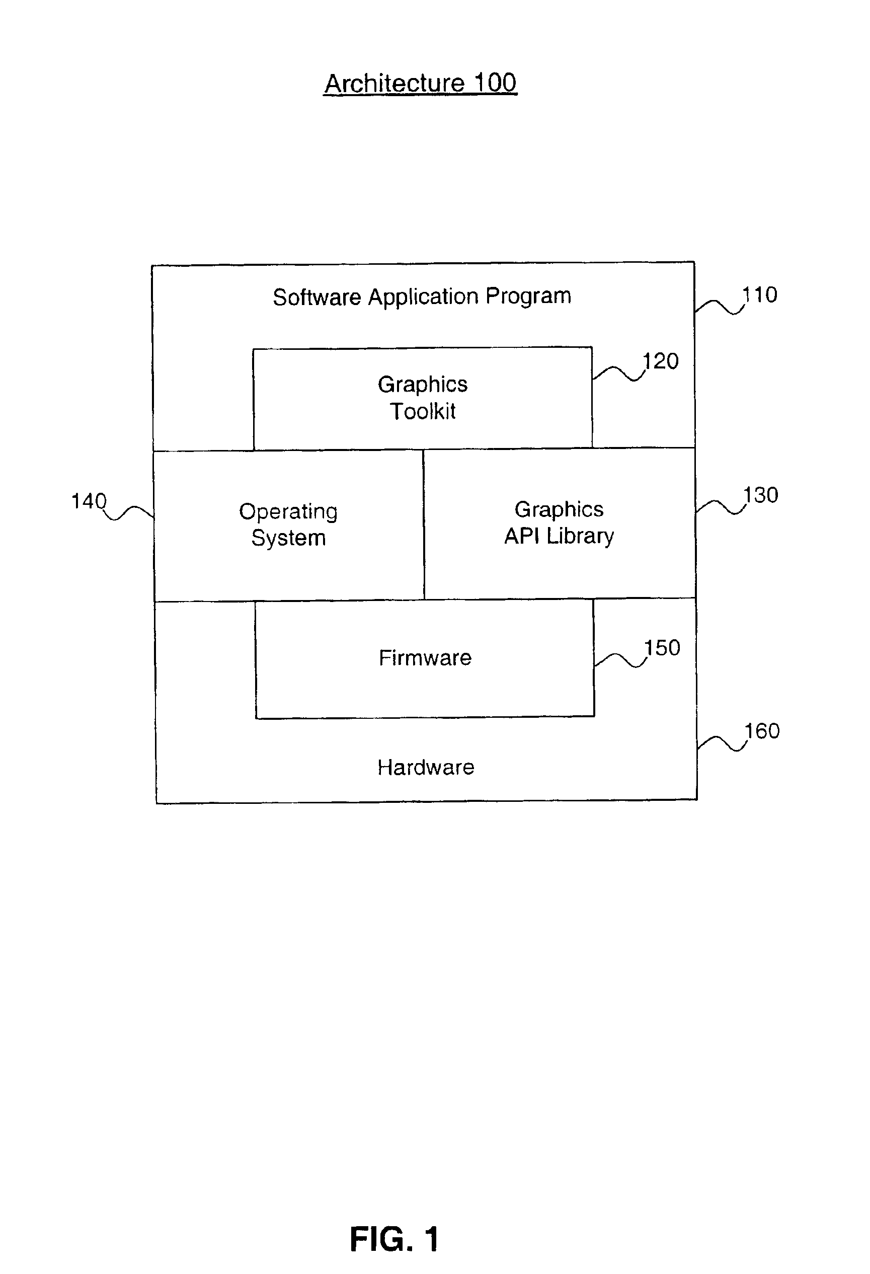
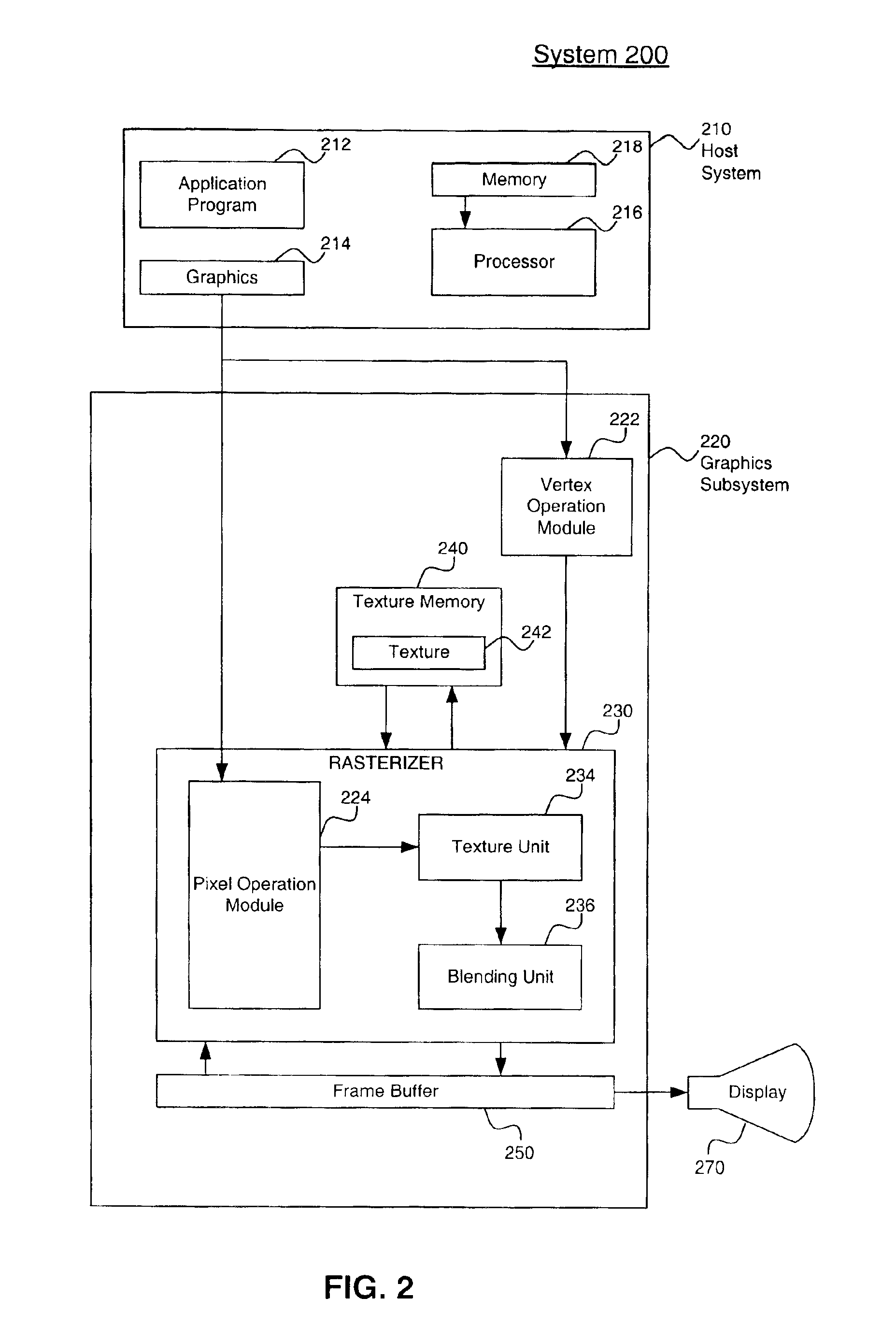
CROSS-REFERENCE TO RELATED APPLICATIONS[0001]This application is a Continuation-in-Part of U.S. application Ser. No. 10 / 197,845, filed Jul. 19, 2002, and this application is also a Continuation-in-Part of U.S. application Ser. No. 10 / 197,822, filed Jul. 19, 2002, now U.S. Pat. No. 6,831,642; both of which are incorporated herein by reference in their entirety.BACKGROUND OF THE INVENTION[0002]1. Field of the Invention[0003]The present invention relates to computer graphics including animation.[0004]2. Related Art[0005]A wide variety of applications rely on computer graphics to generate images. An image is made up of an array of picture elements (pixels) and can be displayed on a display unit, such as, a monitor, screen, or cathode ray tube. Images often include graphical representations of objects. Many different types of computing devices with graphics capabilities are used to generate images. Such computing devices use graphics processing. A combination of software, firmware and / or...

Claims


Application Information

Patent Timeline
Patent Type & Authority Patents(United States)
IPC IPC(8): G06F17/00G06T15/00
CPCG06T13/40G06T13/80G06T15/04G06T17/20
Inventor MECH, RADOMIR
Owner MORGAN STANLEY
Learn More