Device and method for moulding micro-components

a technology of injection device and micro-component, which is applied in the field of injection device for moulding micro-components, can solve the problems of complex and expensive devices, unacceptably high levels of parts having to be rejected, and the device is complex and expensive to implemen

Inactive Publication Date: 2017-10-05
SOPROD SA
View PDF0 Cites 0 Cited by
  • Summary
  • Abstract
  • Description
  • Claims
  • Application Information

AI Technical Summary

Benefits of technology

[0008]Another object of the invention consists in providing a device and method for moulding micro-components enabling a high number of parts to be produced whilst maintaining a level of quality that complies with the often very strict requirements of micro-components designed for high precision mechanisms such as optical elements or parts for watch movements.
[0009]Yet another object of the invention consists in providing a moulding device and method allowing parts of very small dimensions and very low tolerances to be produced with a high degree of reliability and at an advantageous cost.
[0011]Thanks to this architecture, the device according to the invention makes it possible to carry out large batches of mouldings with lots comprising several parts, such as for example 8, 12, 16, 24, 32 parts or even more, depending on the profiles and dimensions.
[0013]The level compensation device is advantageously constituted of a single piece, thus making its integration in pre-existing moulding facilities easier, at reasonable costs.

Problems solved by technology

Furthermore, the configuration with four bars that have to be mounted in a strictly parallel manner requires a very high precision, which makes the device complex and expensive to implement.
However, as soon as the number of cavities is increased, the quality of the parts produced becomes random, causing unacceptably high levels of parts having to be rejected.

Method used


Image

  • Device and method for moulding micro-components
  • Device and method for moulding micro-components
  • Device and method for moulding micro-components

Examples


Embodiment Construction

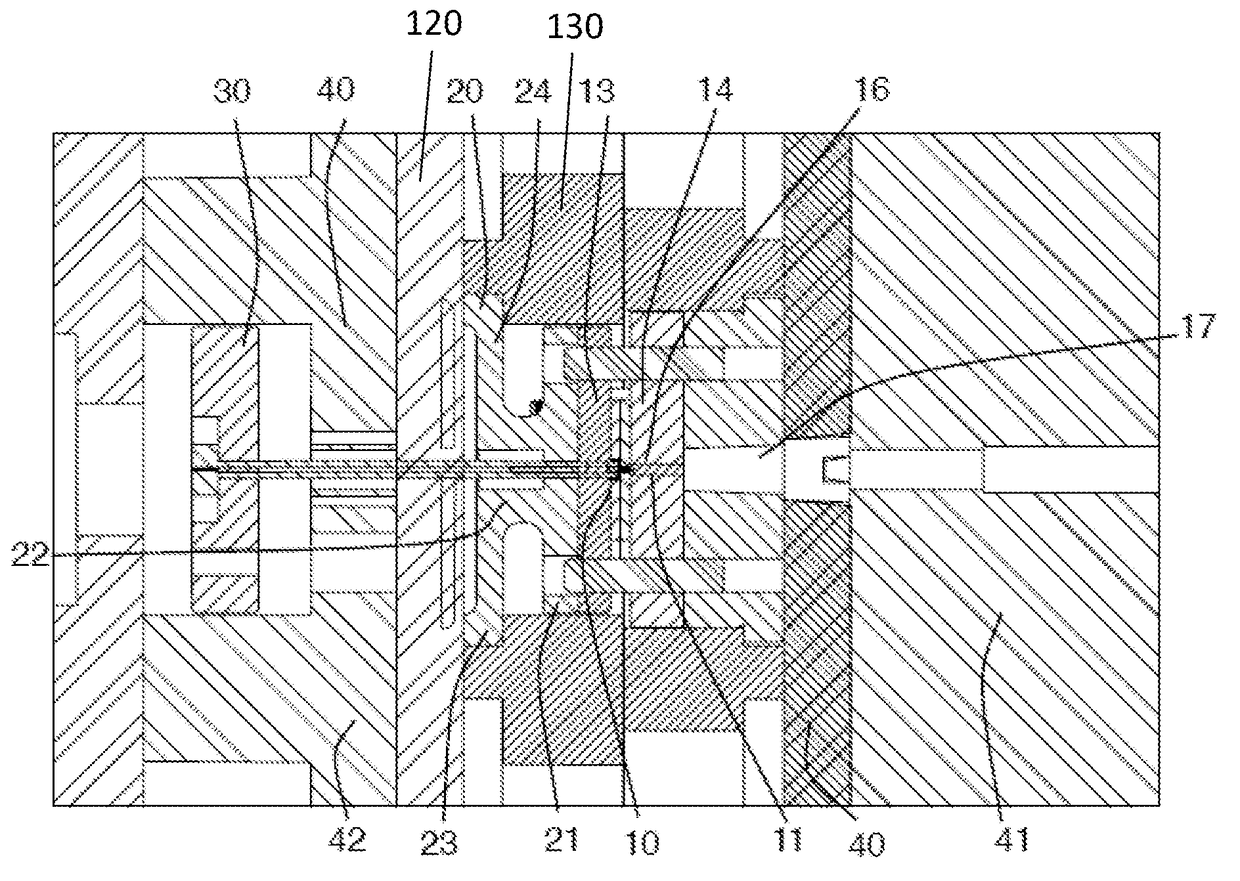
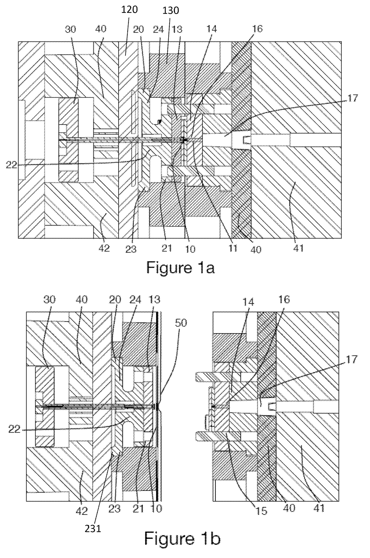
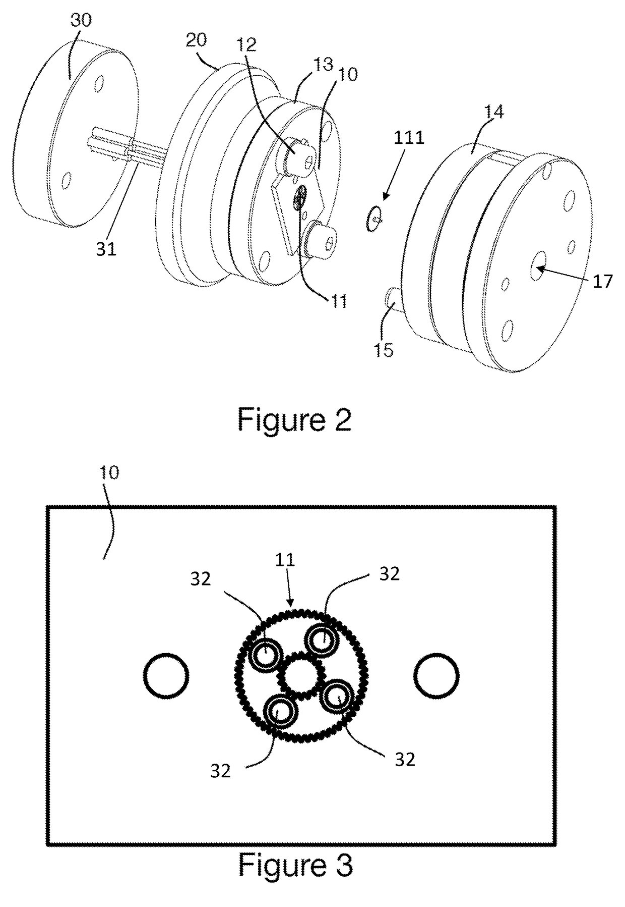
[0027]FIG. 1a illustrates an embodiment in which a mould 10 is constituted of a moulding insert in which a plurality of mould cavities 11 (or recesses or profiles) in the inverse image of the parts to be produced are formed. In the example illustrated, the insert comprises a single mould cavity allowing a toothed wheel with pinion to be moulded.

[0028]A mould support or mould carrier 13 in the form of a disc allows the mould 10 to be positioned and held on one of the faces of the mould carrier. In the example illustrated, two collar retaining bushings 12 (visible in FIG. 2) of the mould support are provided on each side of the latter to ensure it is held against the mould carrier 13. A counter mould 14 is provided opposite the mould 10 and the mould carrier 13. In the illustrated embodiment, the counter mould 14 is also in the shape of a disc, with one side being designed to interface with the mould 10, in order to form the last wall of the mould cavities 11.

[0029]As illustrated in F...


PUM

PropertyMeasurementUnit
temperaturesaaaaaaaaaa
pressureaaaaaaaaaa
elastic areaaaaaaaaaaa

Abstract

A method and device for injection moulding micro-components, including an injection moulding machine having a mould carrier, which supports a removable mould in which at least one mould cavity is provided; and a counter mould, which is arranged so as to be closed against the mould in such a way as to apply a centering force as well as moulding pressure to the mould when the counter mould is closed against the mould.

Description

FIELD OF THE INVENTION[0001]The present invention relates to an injection device (for moulding micro-components) constituted of an injection press in which a mould carrier is placed supporting a removable mould in which at least one mould cavity is provided for moulding, a counter mould arranged for exerting a moulding pressure on the mould. It also relates to a corresponding moulding method.STATE OF THE ART[0002]Patent application EP0272138 describes a method for moulding plastic initiated by injecting molten resin into a mould under high pressure. The two parts of the mobile mould, movable relative to one another, are placed on four clamping bars fastened at the four corners of the mould. These bars have elastic elongation characteristics of a length delta L, in order to compensate a possible parallelism defect between the two adjacent faces of the mould. Due to the fact that the mould must be placed at the center of the four bars, the arrangement can be used only for a small numb...

Claims


Application Information

Patent Timeline
Patent Type & Authority Applications(United States)
IPC IPC(8): B29C45/77B29C45/26B29C45/73B29C45/37B29C45/40
CPCB29C45/77B29C45/376B29C45/4005B29C45/73B29C2945/76498B29C2045/0094B29L2011/0016B29C2945/76866B29C2945/76742B29C45/2606B29C33/303B29C45/561B29C2045/5645
Inventor PITTELOUD, JEAN-CAMIL
Owner SOPROD SA
Why Eureka
Try Eureka